Multi-specification rotary intelligent vending machine and method thereof
An intelligent vending machine, a rotary technology, applied in the directions of coin-operated equipment for distributing discrete items, coin-operated equipment for distributing discrete items, coin-operated equipment for distributing discrete items, etc., can solve the problem of unfavorable utilization. space etc.
Pending Publication Date: 2021-07-09
SHANGHAI DOUBLE THREE LOGISTICS EQUIP +2
12 Cites 0 Cited by
AI-Extracted Technical Summary
Problems solved by technology
[0003] In view of the above-mentioned related technologies, the inventor believes that the unmanned vending machines, automatic storage cabinets, automatic mailing cabinets, and pick-up cabinets in t...
Method used
At least one display screen 13 and touch screen 14 are also installed on the cabinet 1, the display screen 13 and the touch screen 14 are all electrically connected to the control system, and the cabinet 1 is also provided with an information code acquisition device 15, which is convenient for Recognize barcodes and QR codes. The screen and the information code are convenient for establishing a connection between the user and the control system, so that the control system can obtain external information, thereby facilitating the control system to control other mechanisms in the cabinet 1, and the screen can also play the role of advertising, and Multiple screens can increase the display effect of the cabinet body 1 . The bottom inside the cabinet body 1 is provided with a support frame 12 for placing the cargo rack driving mechanism 3 .
The implementation principle of the embodiment of the present application: whether it is a retail device or an automatic storage device related to the storage of goods, in the process of storing goods, the flexible rotating cargo lane can be adjusted according to the storage of goods, so as to facilitate the rational use of space, Moreover, a flexible rotating cargo lane can be rotated to the door opening mechanism 4, so that the taking out of the cargo can be facilitated under the condition of reasonable use of space; and a scanning mechanism is also provided to form the spatial layout of the cargo compartment 27 in the control system, thereby facilitating Realize space management of cargo layout. In the process of picking up the goods, the control system controls the picking lane 26 corresponding to the cargo compartment 27 to rotate to the door opening mechanism 4, and then controls the door opening mechanism 4 to only expose the height and width dimensions of the corresponding cargo compartment 27, so as to facilitate protection of other positions the safety of the goods.
[0051] The cargo storage mechanism 2 includes a cylindrical outer rotator 21 and three inner rotators 22, and the three inner rotators 22 are equidistantly distributed on the circular upper and lower chassis of the outer rotator 21. The rotation axis of the inner rotating body 22 is parallel to the rotating axis of the outer rotating body 21, and the inner rotating body 22 is rotatably connected in the outer rotating body 21, and the diameter of the inner rotating body 22 is smaller than or equal to the radius of the outer rotating body 21. The inner rotator 22 is provided with a cargo delivery lane 26 whose op...
Abstract
The invention relates to a multi-specification rotary intelligent vending machine and a method thereof. The multi-specification rotary intelligent vending machine comprises a cabinet body, a goods storage mechanism arranged in the cabinet body, a goods shelf driving mechanism, a door opening mechanism, a goods lattice scanning mechanism and a control system; the goods storage mechanism comprises a plurality of flexible rotating goods channels, and a plurality of goods grids are arranged in the flexible rotating goods channels; the goods shelf driving mechanism is arranged; the door opening mechanism comprises an uncoiling gate assembly and a sliding door assembly, and when a piece is taken, the uncoiling gate assembly and the sliding door assembly are opened till a goods lattice where goods are to be taken is exposed; a goods scanning mechanism comprises a scanning assembly and a scanning driving part for driving the scanning assembly to be close to or away from goods lattices; the control system is electrically connected with the goods shelf driving mechanism, the door opening mechanism and the goods lattice scanning mechanism, and the control system generates the spatial layout of all the goods lattices in the system according to the goods lattice distribution situation sensed and obtained by the goods scanning mechanism.The spatial layout of all the goods lattices is generated in the system. The multi-specification rotary intelligent vending machine has the effect of improving the space utilization rate of the goods storage device of the vending machine.
Application Domain
Coin-freed apparatus detailsApparatus for dispensing discrete articles
Technology Topic
Control systemControl engineering +2
Image
Examples
- Experimental program(1)
Example Embodiment
[0047] The following is attached Figure 1-8 The application is described in further detail.
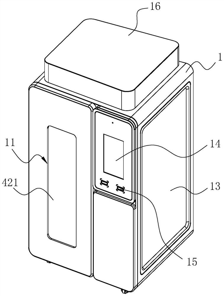
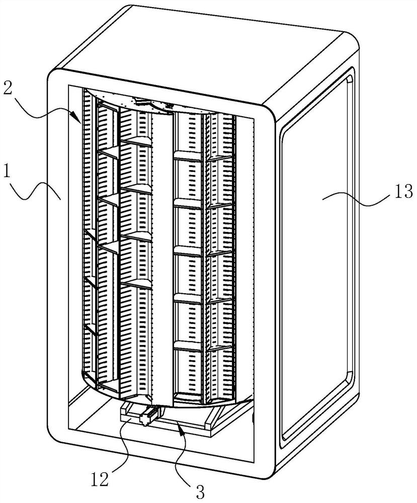
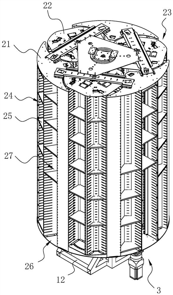
[0048] The embodiment of the present application discloses a multi-standard rotary intelligent vending machine. refer to figure 1 and figure 2 , The multi-standard rotary intelligent vending machine includes a cabinet body 1. The cabinet body 1 is in the shape of a square prism as a whole, and a square light box 16 is arranged on the top, and four universal wheels capable of self-locking are installed at the four corners of the bottom. The cabinet body 1 is built with a cargo storage mechanism 2, a cargo rack driving mechanism 3 for driving the cargo storage mechanism 2 to rotate, a door opening mechanism 4, a cargo grid scanning mechanism 5, and a control system. The control system is electrically connected with the cargo rack driving mechanism 3, the door opening mechanism 4 and the cargo grid scanning mechanism 5, and is used to control the rotation of the cargo rack driving mechanism 3 and the working state of the door opening mechanism 4, and obtain position data and The data is stored, and the control system fits the spatial layout data of the scanned cargo compartment 27 according to the position data and the stored data.
[0049] At least one display screen 13 and touch screen 14 are also installed on the cabinet 1, the display screen 13 and the touch screen 14 are all electrically connected to the control system, and the cabinet 1 is also provided with an information code acquisition device 15, which is convenient for identifying barcodes and QR code. The screen and the information code are convenient for establishing a connection between the user and the control system, so that the control system can obtain external information, thereby facilitating the control system to control other mechanisms in the cabinet 1, and the screen can also play the role of advertising, and Multiple screens can increase the display effect of the cabinet body 1 . The bottom inside the cabinet body 1 is provided with a support frame 12 for placing the cargo rack driving mechanism 3 .
[0050] refer to image 3 , the cargo storage mechanism 2 includes a plurality of flexible rotating cargo lanes, and a plurality of adjustable cargo grids 27 are arranged in the flexible rotating cargo lanes.
[0051] The cargo storage mechanism 2 includes a cylindrical outer rotator 21 and three inner rotators 22 , and the three inner rotators 22 are equidistantly distributed on the circular upper and lower chassis of the outer rotator 21 . The rotation axis of the inner rotating body 22 is parallel to the rotating axis of the outer rotating body 21, and the inner rotating body 22 is rotatably connected in the outer rotating body 21, and the diameter of the inner rotating body 22 is smaller than or equal to the radius of the outer rotating body 21. The inner rotator 22 is provided with a cargo delivery lane 26 whose opening is far away from the direction of its own rotation axis along a direction parallel to its axial direction, and the outer rotator 21 is provided with an opening for the delivery cargo lane 26 on the inner rotator 22 to expose. In the position area 23, the outer rotating body 21 is also provided with a plurality of pick-up lanes 26 away from its own rotation axis along the circumferential direction, and a plurality of slots 24 are provided at equal intervals along the length direction in the pick-up lane 26, and the slots 24 is plugged with a board 25 that is adapted to the cross-sectional shape of the slot 24 . The cargo picking lanes 26 on the inner rotating body 22 and the outer rotating body 21 form the above-mentioned flexible rotating cargo lanes, and the inserting boards 25 separate the picking cargo lanes 26 to form a plurality of cargo compartments 27 . The size of the cargo lattice 27 can be adjusted according to the storage of goods. Intersecting the storage space arranged in a planar array, the flexible rotating goods lanes on the inner rotating body 22 and the outer rotating body 21 make full use of the space, and the outer rotating body 21 is also provided with a cargo picking lane 26 to fully improve the quality of goods. For the space utilization rate of the storage mechanism 2, when items corresponding to the compartment 27 are needed, the control system will rotate the corresponding compartment 27 to the door opening mechanism 4, so as to realize the steps for the user to pick up the goods.
[0052] refer to Figure 4 , the cargo rack driving mechanism 3 is installed on the support frame 12, and is used to drive the flexible rotating cargo lane to rotate to the cargo grid 27 to be picked up corresponding to the door opening mechanism 4, and generate position data for the flexible rotating cargo lane to rotate.
[0053] The cargo rack driving mechanism 3 includes a main driving assembly 31 and an auxiliary driving assembly 32 , the main driving assembly 31 includes a main motor 311 and a first transmission member 312 , and the main motor 311 drives the outer rotating body 21 to rotate through the first transmission member 312 . The first transmission member 312 is set as a gear transmission, and bearings are provided between the central rotating shafts at both ends of the outer rotating body 21 and the support frame 12 and the cabinet body 1 respectively. The auxiliary drive assembly 32 includes an auxiliary motor 321 and a second transmission member 322. The auxiliary motor 321 drives the three inner rotating bodies 22 to rotate synchronously and in the same direction through the second transmission member 322. The second transmission member 322 is configured as a transmission wheel and a conveyor belt. Rotary bearings are installed between the two ends of the rotating shaft of the inner rotating body 22 and the outer rotating body 21 . According to the obtained pick-up information, the control system controls the main motor 311 to drive the movement of the outer rotator 21, and controls the auxiliary motor 321 to drive the three inner rotators 22 to rotate synchronously, so that all the compartments 27 to be picked up can be rotated to the door opening mechanism 4 places.
[0054] refer to Figure 5 , in order to increase the safety of other goods during the pick-up process, two-layer doors are provided. The cabinet body 1 is provided with a pick-and-place cargo opening 11, and the door opening mechanism 4 includes an unwinding gate assembly 41 and a translation door assembly. A translation door assembly 42, The unwinding gate assembly 41 and the translation door assembly 42 are stacked. Preferably, the translation door assembly, the translation door assembly 42 is located on the outside, and the unwinding gate assembly 41 is located on the inside. During pick-up, the unwinding gate assembly 41 and the translation door assembly 42 are respectively opened to expose the cargo compartment 27 to be picked up.
[0055] Wherein, the unwinding gate assembly 41 includes two groups of rolling gates with opposite opening directions, and the rolling gates include a ball screw 411 , a screw driver 412 , a reel 413 , a return coil spring 414 sleeved on the reel 413 and a reeling door 415 . The ball screw 411 is fixedly connected to the cabinet body 1 and arranged along the length direction parallel to the flexible rotating shelf 27 . The screw driver 412 is set as a motor, which is fixedly connected in the cabinet body 1 to drive the screw in the ball screw 411 to rotate. One end of the rolling door 415 is fixedly connected with the reset coil spring 414, and the other end is connected with the ball screw 411. The sliders in are fixedly connected. The two lead screw drive parts 412 are controlled and connected to the control system, and the control system sends separate drive signals to the two lead screw drive parts 412 according to the spatial layout formed by the scanning information of the scanning mechanism, so that the upper and lower groups of rolling shutters Open to the set position.
[0056] Translation door assembly The translation door assembly 42 includes a direction plate-shaped translation door 421 and a translation driver 422 fixed in the cabinet body 1 . The translation door 421 is slidably connected to the inner side of the loading and unloading port 11, and the translation driver 422 is controlled and connected to the control system, and the control system sends a driving signal to drive the translation driver 422 to drive the translation door 421 to open to a set position. The translation driving part 422 drives the translation door 421 to be slidably connected in the cabinet body 1 to realize the movement of the translation door 421, and the translation door 421 located inside has better safety. The translation driving part 422 is composed of a driving motor and a rack and pinion transmission, so as to realize the translation action of the translation door 421 .
[0057] Among them, after the control system receives the pick-up information, the corresponding cargo compartment 27 is rotated to the door opening mechanism 4, and the control system controls the two opposite rolling shutters located on the inner side to open to the height position corresponding to the cargo compartment 27; The door 421 is opened to expose the width of the corresponding compartment 27, so that only one gap of the compartment 27 is exposed for the user to pick up the goods, which is safe and convenient, and protects the safety of other goods.
[0058] refer to Image 6 , the cargo scanning mechanism, including acquiring the scanning component and driving the scanning component close to or away from the scanning driver 53 of the cargo grid 27, the scanning component is used to generate storage data for the storage state of the cargo grid 27, and the scanning driver 53 is used to sense the flexible rotating cargo The distribution of goods price 27 in the road.
[0059] The scanning assembly comprises a support plate 51 and sensors 52 mounted on the support plate 51 in rows, the spacing between adjacent sensors 52 is equal to the spacing between the slots 24, and the support plate 51 is arranged along the length direction parallel to the delivery lane 26 , the sensor 52 is set as a proximity sensor 52 . The sensor 52 is used for one-to-one correspondence with the slots 24 on the picking lane 26, any picking lane 26 rotates to the scanning mechanism, and the scanning driver 53 drives the scanning assembly close to the picking lane 26 to detect the slot 24 Whether there is an inserting board 25 at the place, the scanning driver 53 is used to drive the supporting board 51 to approach or move away from the goods picking lane 26 . The driving mode of the scanning driving member 53 adopts a short cylinder driving or a driving mode of a motor, a gear and a rack.
[0060] The sensors 52 arranged in rows are used as the scanning mechanism of the cargo grid 27. When the cargo picking channel 26 rotates to the scanning mechanism, the scanning driver 53 drives the support plate 51 and the sensor 52 close to the cargo grid 27 to detect whether the slot 24 is There is a plugboard 25, so that the detection signal of the sensor 52 is given to the control system. After scanning a pick-up lane 26, continue to rotate the next pick-up lane 26 to the scanning mechanism, and finally the control system generates the spatial layout of the cargo grid 27.
[0061] In addition, refer to Figure 7 The cargo driving mechanism also includes a positioning verification assembly 7, which is arranged between the inner rotating body 22 and the outer rotating body 21, and between the outer rotating body 21 and the cabinet body 1, and is used to verify the alignment between the outer rotating body 21 and the outer rotating body 21. Whether the rotation of the inner rotating body 22 is in place. The positioning verification component 7 can play a role of feedback, facilitating the precise control of the inner rotating body 22 and the outer rotating body 21 .
[0062] refer to Figure 8 In order to improve the safety of the goods, especially in the case of a power failure, the outer rotating body 21 does not rotate relative to the support frame 12, and the inner rotating body 22 does not rotate relative to the outer rotating body 21. Including the anti-theft mechanism 8, the anti-theft mechanism 8 is arranged on the support frame 12, the anti-theft mechanism 8 includes a power-off switch 81, the outer rotating body 21 is provided with a first limiting hole 82, and the inner rotating body 22 is provided with a second limiting hole 83; after the power is cut off, the switch pin of the power-off switch 81 is stretched out and inserted into the first limiting hole 82 and the second limiting hole 83 in order to limit the relative rotation between the inner rotating body and the outer rotating body 21 . That is, the cargo storage mechanism 2 is not easy to be rotated arbitrarily, and to ensure the stability of the cargo storage mechanism 2 during transportation, and to cut off the power when the door is opened, the inner rotator 22 and the outer rotator 21 are not easily rotated.
[0063]The implementation principle of the embodiment of the application: Whether it is a retail device or an automatic storage device that involves storage of goods, in the process of storing goods, the flexible rotating cargo lane can be adjusted according to the storage of goods, which is convenient for the rational use of space, and is equipped with The flexible revolving cargo lane can be rotated to the door opening mechanism 4, so as to facilitate the taking out of the cargo under the condition of reasonable use of space; and a scanning mechanism is also provided to form the spatial layout of the cargo compartment 27 in the control system, so as to facilitate the realization of the cargo layout space management. In the process of picking up the goods, the control system controls the picking lane 26 corresponding to the cargo compartment 27 to rotate to the door opening mechanism 4, and then controls the door opening mechanism 4 to only expose the height and width dimensions of the corresponding cargo compartment 27, so as to facilitate protection of other positions the safety of the goods.
[0064] The embodiment of the present application also discloses a multi-standard rotary intelligent vending machine vending method, based on the above-mentioned multi-standard rotary intelligent vending machine,
[0065] refer to Figure 9 , including the following steps:
[0066] The control system controls the scanning mechanism to scan the picking lanes 26 where the items are placed one by one, and generates the spatial layout of the picking lanes 26 in the control system; the above-mentioned sensor 52 is also used to sense the position of the inserting board 25 for scanning.
[0067] The control system acquires the information of the items to be picked up, and controls the cargo rack driving mechanism 3 to drive the cargo storage mechanism 2 to rotate to align the cargo compartment 27 corresponding to the item to be picked up with the door opening mechanism 4 according to the item to be picked up information;
[0068] The control system calculates the height and position of the cargo compartment 27 corresponding to the information to be picked up according to the spatial layout, opens the unrolling gate assembly 41 to the set height, and controls the translation door assembly to open the translation door assembly 42 to the set width; The width of the picking compartment 27 in the application is consistent, which is convenient for the control of the opening width of the translation door 421.
[0069] After the cargo grid 27 is shipped, the control system controls the door-opening mechanism 4 to reset.
[0070] In addition, when the goods in the goods storage mechanism 2 are insufficient, the control system promptly reminds the staff to replenish goods according to the situation of picking up goods. For example, when the quantity of the goods not taken out in the compartment 27 is less than 10, the control system sends replenishment information to the staff.
[0071] The implementation principle of a multi-standard rotary intelligent vending machine and its method in the embodiment of the present application is as follows: the scanning mechanism realizes the scanning of the cargo storage mechanism 2, and the control system realizes the spatial layout of the cargo compartment 27 according to the scanning results of the scanning mechanism, so as to facilitate The management of goods is convenient to control the opening height of the door opening mechanism 4 and the angle of rotation setting of the cargo storage mechanism 2 .
[0072] All of the above are preferred embodiments of the application, and are not intended to limit the protection scope of the application. Therefore, all equivalent changes made according to the structure, shape, and principle of the application should be covered by the protection scope of the application. Inside.
PUM


Description & Claims & Application Information
We can also present the details of the Description, Claims and Application information to help users get a comprehensive understanding of the technical details of the patent, such as background art, summary of invention, brief description of drawings, description of embodiments, and other original content. On the other hand, users can also determine the specific scope of protection of the technology through the list of claims; as well as understand the changes in the life cycle of the technology with the presentation of the patent timeline. Login to view more.