Method and apparatus in node used for wireless communication
A technology of wireless communication and node equipment, which is applied in the field of node neutralization devices used for wireless communication, and can solve problems such as inability to work and ineffective work in design, to ensure random access capacity, avoid signaling overhead, and reduce The effect of power consumption
- Summary
- Abstract
- Description
- Claims
- Application Information
AI Technical Summary
Problems solved by technology
Method used
Image

Examples
Embodiment 1
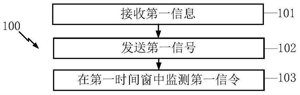
[0085] Embodiment 1 exemplifies a flow chart of first information, first signal, and first signaling according to an embodiment of the present application. figure 1 Indicated. With figure 1 In each box, each box represents a step, in particular, it is important to emphasize the order in which each block in the figure does not mean that the steps indicated between the steps are in time.
[0086] In Embodiment 1, the first node device in the present application receives the first information in step 101, the first information being used to determine the first length of length, the first length of length than 0; in step 102 The first signal is transmitted, and the time-frequency resource occupied by the first signal is used to indicate the first identification; in step 103, the first signal is monitored, the first identification being used for the Monitoring of the first signaling; the first signal includes X sub-signal, the X is a positive integer greater than 1, and the first symbol ...
Embodiment 2
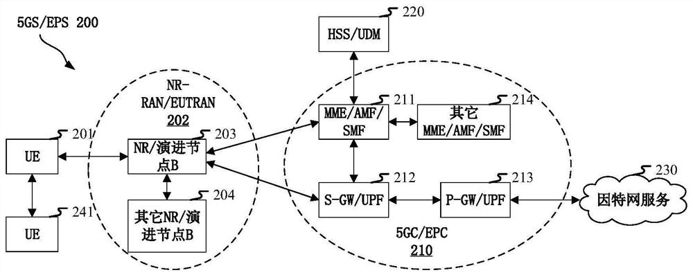
[0298] Embodiment 2 illustrates a schematic diagram of a network architecture according to the present application, figure 2 Indicated. Attach figure 2 A map of the network architecture 200 of 5G NR, LTE (Long-Term Evolution, long evolution) and LTE-A (Long-Term Evolution Advanced, enhanced long-term evolution) system. 5G NR or LTE Network Architecture 200 can be referred to as 5GS (5G System) / EPS (Evolved Packet System, Evolution Packet System) 200 Some other suitable terms. 5GS / EPS 200 can include one or more UE (User Equipment, User Equipment) 201, NG-RAN (next-generation wireless access network) 202, 5GC (5G Core Network, 5G core network) / EPC (Evolved Packet Core, Evolution Group Core) 210, HSS (Home Subscriber Server, Home Sign User Server) / UDM (Unified Data Management) 220 and Internet Services 230.5GS / EPS can interconnect with other access networks, but for simple Demonstrate these entities / interfaces. As shown, 5GS / EPS provides package exchange services, howe...
Embodiment 3
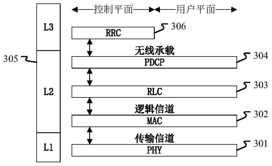
[0312] Embodiment 3 shows a schematic diagram of an embodiment of a wireless protocol architecture according to a user plane and a control plane according to the present application. image 3 Indicated. image 3 It is a schematic diagram illustrating an embodiment of a radio protocol architecture for user plane and control plane, image 3 The radio protocol architecture for the first node device (UE) and a second node device (satellite or aircraft in GNB, ENB or NTN) is shown in three layers: layer 1, layer 2 and layer 3. The layer 1 (L1 layer) is the lowest layer and performs various PHY (physical layer) signal processing functions. The L1 layer will be referred to herein as PHY301. The layer 2 (L2 layer) 305 is above the PHY301 and is responsible for link between the PHY 301 in the first node device and the second node device. In the user plane, the L2 layer 305 includes MAC (Medium Access Control, Media Access Control) sub-layer 302, RLC (Radio Link Control, Radio Link Layer Contr...
PUM
 Abstract
Description
Claims
Application Information
 - R&D Engineer
- R&D Manager
- IP Professional
- Industry Leading Data Capabilities
- Powerful AI technology
- Patent DNA Extraction
Browse by: Latest US Patents, China's latest patents, Technical Efficacy Thesaurus, Application Domain, Technology Topic.
© 2024 PatSnap. All rights reserved.Legal|Privacy policy|Modern Slavery Act Transparency Statement|Sitemap