Adaptive animation camera used in case of slope changes
A camera and animation technology, which is applied in the direction of supporting machines, mechanical equipment, machine platforms/supports, etc., can solve problems such as large vibration amplitudes, unsatisfactory levels of tracks, and vibrations of animation cameras, so as to reduce wear, prolong service life, reduce The effect of small impact
- Summary
- Abstract
- Description
- Claims
- Application Information
AI Technical Summary
Problems solved by technology
Method used
Image
Examples
Embodiment 1
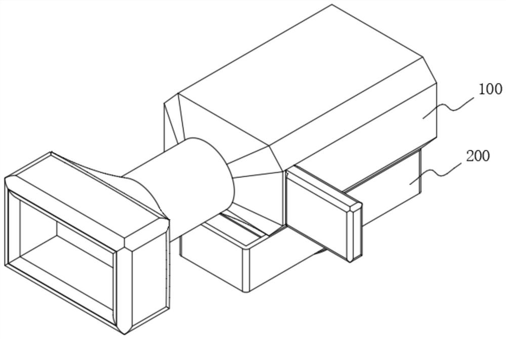
[0053] See Figure 1-Figure 4 As shown, the object of the present embodiment is to provide an animation camera adapted to the use of slope changes, comprising an animation camera body 100, the animation camera body 100 is provided with a motion balancing device 200 at the bottom, a motion balancing device 200 comprises at least:
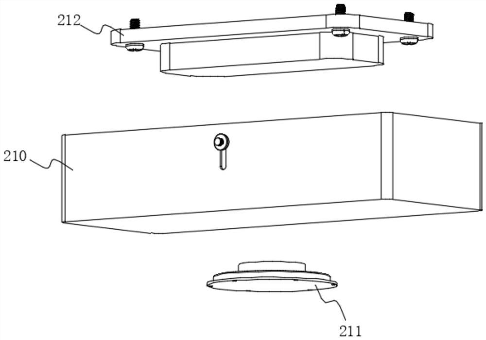
[0054] Housing 210, housing 210 is provided with a connection plate 212 at the top;
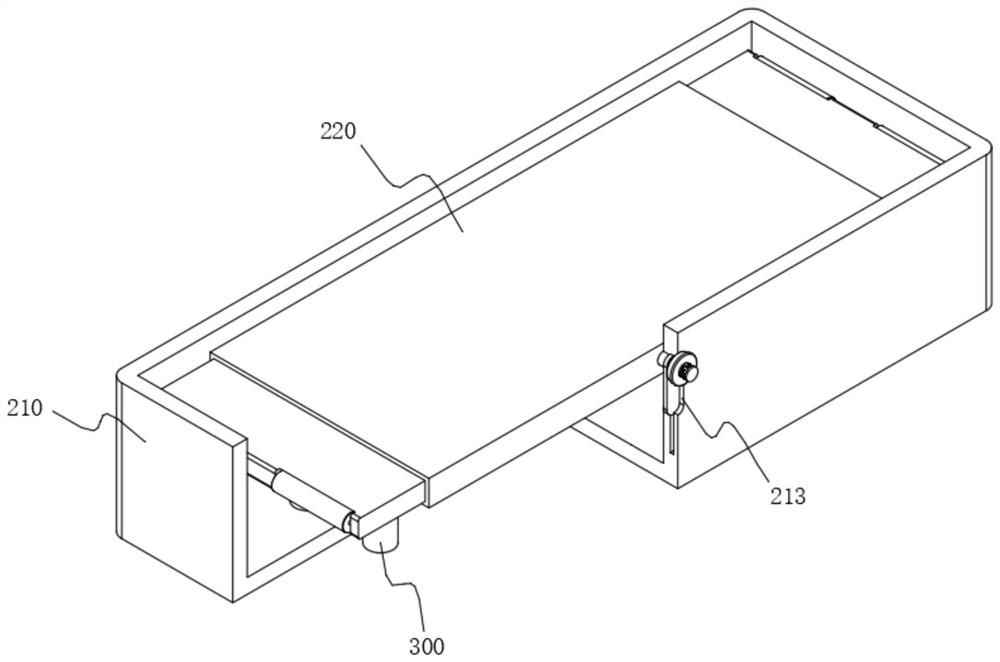
[0055] Balance plate 220, balance plate 220 is fixed by connecting the plate 212 and the animation camera body 100, and the balance plate 220 is provided with a liquid balance mechanism 230 at the bottom, the liquid balance mechanism 230 includes a sleeve 231, the sleeve 231 is an opening upward "U" shaped structure, the two ends of the sleeve 231 slide connection with the balance plate 220 rotation connection of the balance column 232, the balance column 232 and the sleeve 231 are connected to form a "U" shaped balance chamber, the balance chamber is filled with liquid;...
Embodiment 2
[0059] In order to buffer the longitudinal vibration force of the balance plate 220, the present embodiment is different from Example 1, see Figure 6 as shown, where:
[0060] Elastic buffer 300 is disposed on both sides of the liquid balance mechanism 230, the elastic buffer 300 includes a buffer seat 310, the top sliding connection of the buffer seat 310 is connected to the buffer column 320, and the buffer column 320 and the buffer seat 310 are fixedly connected to the buffer spring 330, for the buffer column 320 in conjunction with the longitudinal vibration force generated by the balance plate 220 to buffer.
[0061] It's worth noting that see Figure 7 As shown, wherein the buffer column 320 and the balance plate 220 reserved a certain distance, to provide an adaptation distance for the balance plate 220, to avoid the buffer spring 330 itself jitter caused by the balance plate 220 to shake.
[0062] Whether in orbital motion, or manual movement, when the animation camera body...
Embodiment 3
[0064]In order to make the height of the buffer column 320 adjust with the inclination of the balance plate 220, the present embodiment is different from Example 2, see Figure 11 and Figure 12 as shown, where:
[0065] Between the casing 231 and the buffer seat 310 is provided with a connecting tube 340, the sleeve 231 and the buffer seat 310 are connected by the connecting tube 340 to form an integrated cavity, and the buffer spring 330 is fixed at the bottom of the buoyancy plate 311 with the active connection to the buffer seat 310, in addition, the inside of the buffer seat 310 is provided with a limit ring 312.
[0066] The present embodiment in the specific use of the reference Figure 13 As shown, when the casing 231 is tilted, since the connecting tube 340 will connect the casing 231 and the buffer seat 310 into a single cavity, therefore, after tilting, the buoyancy plate 311 at the bottom of the buffer column 320 on the tilt side will be driven by the action of water buoy...
PUM
 Abstract
Description
Claims
Application Information
 - R&D
- Intellectual Property
- Life Sciences
- Materials
- Tech Scout
- Unparalleled Data Quality
- Higher Quality Content
- 60% Fewer Hallucinations
Browse by: Latest US Patents, China's latest patents, Technical Efficacy Thesaurus, Application Domain, Technology Topic, Popular Technical Reports.
© 2025 PatSnap. All rights reserved.Legal|Privacy policy|Modern Slavery Act Transparency Statement|Sitemap|About US| Contact US: help@patsnap.com


