U-shaped workpiece face milling tool with automatic leveling function

An automatic leveling and U-shaped technology, which is applied in the direction of metal processing machinery parts, positioning devices, milling machine equipment, etc., can solve the problems of undiscovered patent documents, damage to the straight side wall of the workpiece, and low positioning efficiency, so as to avoid the surface of the workpiece damage, reduce the difficulty of positioning, and fast positioning

Inactive Publication Date: 2021-07-16
TIANJIN BAOLAI PRECISION MACHINERY
View PDF0 Cites 0 Cited by
  • Summary
  • Abstract
  • Description
  • Claims
  • Application Information

AI Technical Summary

Problems solved by technology

[0002] In the field of workpiece machining with high precision requirements, the milling of U-shaped workpieces is one of the most common machining operations. It is well known that the workpiece needs to be fixed and clamped in milling, but for some U-shaped workpieces, It cannot be clamped directly by the tooling vice in the prior art, especially for U-shaped workpieces. In the prior art, an inner support block is usually processed to be fixed and supported inside the U-shaped workpiece, and then two U-shaped workpieces are clamped. The middle part of the U-shaped workpiece can be cleaned and processed only if the straight side wall is used. However, this clamping method needs to pre-process the inner support block, and the straight side wall of the workpiece is easy to be damaged during the clamping process, and the positioning efficiency is low.
[0003] Through the search of published patent documents, no published patent documents identical to this patent application have been found

Method used


Image

  • U-shaped workpiece face milling tool with automatic leveling function
  • U-shaped workpiece face milling tool with automatic leveling function
  • U-shaped workpiece face milling tool with automatic leveling function

Examples


Embodiment Construction

[0017] In order to further understand the content, characteristics and effects of the present invention, the following examples are given, and detailed descriptions are given below with reference to the accompanying drawings. It should be noted that this embodiment is descriptive, not restrictive, and cannot thereby limit the protection scope of the present invention.

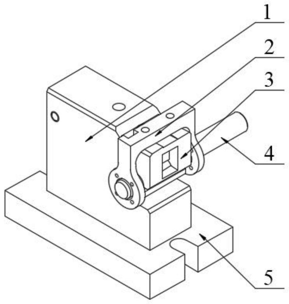
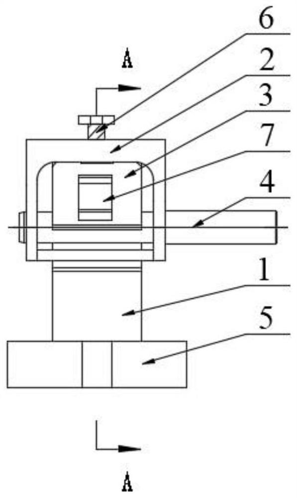
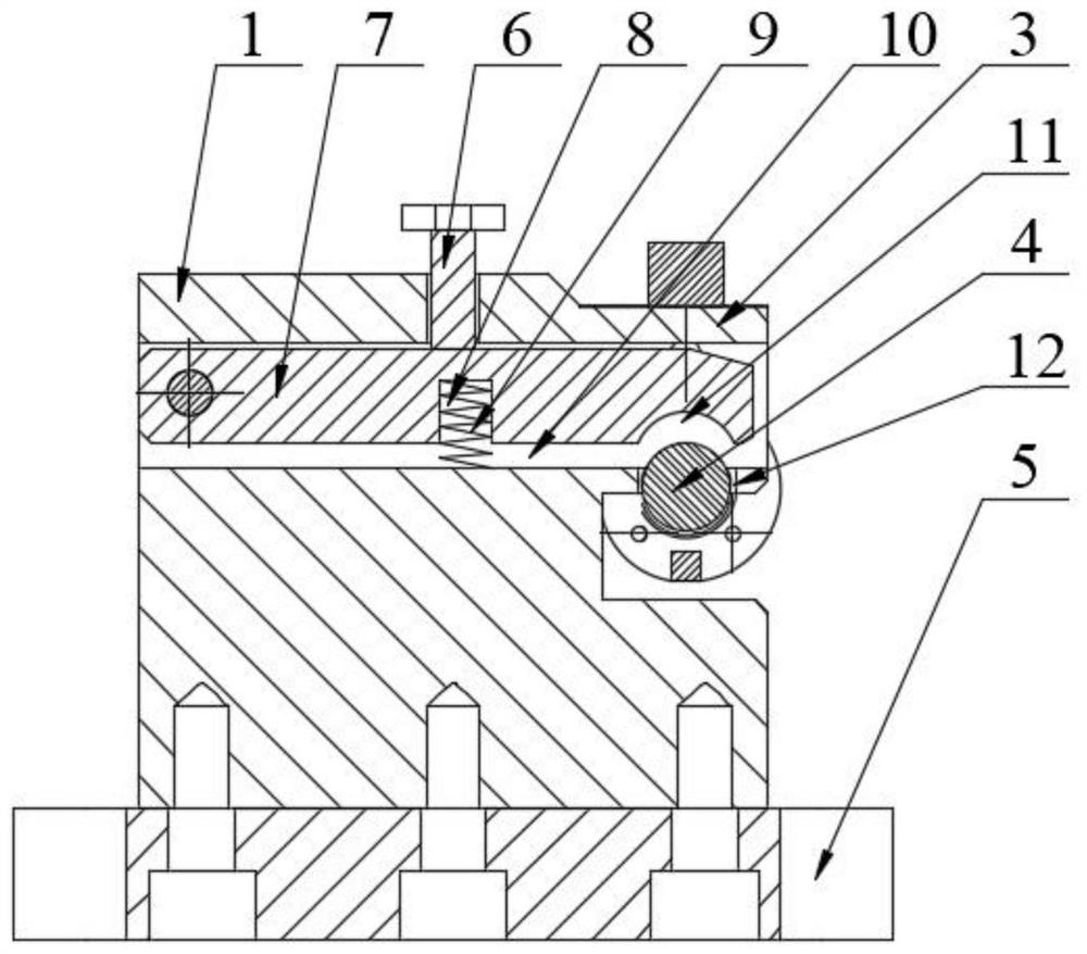
[0018] A U-shaped workpiece surface milling tool with automatic leveling function. The middle part of the U-shaped workpiece 2 is the processing surface. Straight plates are made at both ends of the U-shaped workpiece, and reserved holes are opened on the straight plates. Its innovation In that: the milling tool includes a base 5, a support block 1 is fixed vertically on the top surface of the base; a square hole 10 is formed on the top of the support block, and a horizontally through square hole 10 is formed on the top of the support block, and one end of the square hole axially protrudes from the support block...


PUM


Abstract

The invention relates to a U-shaped workpiece face milling tool with an automatic leveling function. The middle of a U-shaped workpiece is a machining face, straight plates are manufactured at the two ends of the U-shaped workpiece, and preformed holes are formed in the straight plates; the face milling tool comprises a base, and a supporting block is vertically and fixedly installed on the top face of the base; a transversely-through square hole is formed in the upper portion of the supporting block, a positioning square pipe fixedly connected with the side wall of the supporting block axially extends out of one end of the square hole, and a pressing block is hinged to the inner wall of the other end of the square hole; the to-be-machined workpiece is hung on the top face of the positioning square pipe, and the lower portion of the positioning square pipe is transversely connected with a pin shaft in a penetrating manner, wherein the pin shaft is installed in the multiple preformed holes in a penetrating manner; and the free end of the pressing block extends into the positioning square pipe, and the bottom face of the free end of the pressing block is provided with an arc-shaped concave face matched with the radian of the periphery of the pin shaft. The face milling tool does not need to clamp the side wall of the workpiece, so that clamping damage to the surface of the workpiece is avoided, the clamping speed is high, the positioning precision is high, and the face milling tool is particularly suitable for face milling machining of the bottom faces of large-batch U-shaped workpieces.

Description

technical field [0001] The invention relates to the technical field of mechanical tooling, in particular to a U-shaped workpiece surface milling tool with an automatic leveling function. Background technique [0002] In the field of workpiece machining with high precision requirements, the milling of U-shaped workpieces is one of the most common machining operations. It is well known that the workpiece needs to be fixed and clamped in milling, but for some U-shaped workpieces, It cannot be clamped directly by the tooling vice in the prior art, especially for U-shaped workpieces. In the prior art, an inner support block is usually processed to be fixed and supported inside the U-shaped workpiece, and then two U-shaped workpieces are clamped. The middle part of the U-shaped workpiece can be surface-washed only if the straight side wall is used. However, this clamping method needs to pre-process the inner support block, and the straight side wall of the workpiece is easy to be ...

Claims


Application Information

Patent Timeline
Patent Type & Authority Applications(China)
IPC IPC(8): B23C3/00B23Q3/06
CPCB23C3/00B23Q3/062
Inventor 崔超崔越崔文来崔建涛崔雅臣李绍功张涛李绍德
Owner TIANJIN BAOLAI PRECISION MACHINERY
Why Eureka
Try Eureka