
Synchronous reversing valve for oxygen-enriched heating furnace

A heating furnace and reversing valve technology, applied to valve details, multi-way valves, valve devices, etc., can solve problems such as poor synchronization of four-way valve switching actions

Inactive Publication Date: 2021-07-16
张作帅
View PDF0 Cites 0 Cited by
  • Summary
  • Abstract
  • Description
  • Claims
  • Application Information

AI Technical Summary

Problems solved by technology

[0004] Most of the current oxygen-enriched heating furnaces use dual-fluid preheating, that is, to preheat the gas and oxygen-enriched air separately. The preheating of each fluid requires two regenerators connected to the heating furnace on the heating furnace. The two regenerators alternately carry out exhaust gas output and fluid input. In order to realize the alternate exhaust gas output and fluid input of the two regenerators, it is necessary to use a four-way valve to connect the pipelines. The two regenerators are alternately controlled by the four-way valve. Exhaust gas output and fluid input; however, for the double-fluid preheating of the oxygen-enriched heating furnace, in order to ensure the full combustion of the gas and avoid explosions, it is necessary to control the switching actions of the two four-way valves synchronously. The traditional four-way The switching actions of the valves are carried out separately, and there is a problem of poor synchronization of the switching actions of the two or four-way valves

Method used


Image

  • Synchronous reversing valve for oxygen-enriched heating furnace
  • Synchronous reversing valve for oxygen-enriched heating furnace
  • Synchronous reversing valve for oxygen-enriched heating furnace

Examples


Embodiment 1

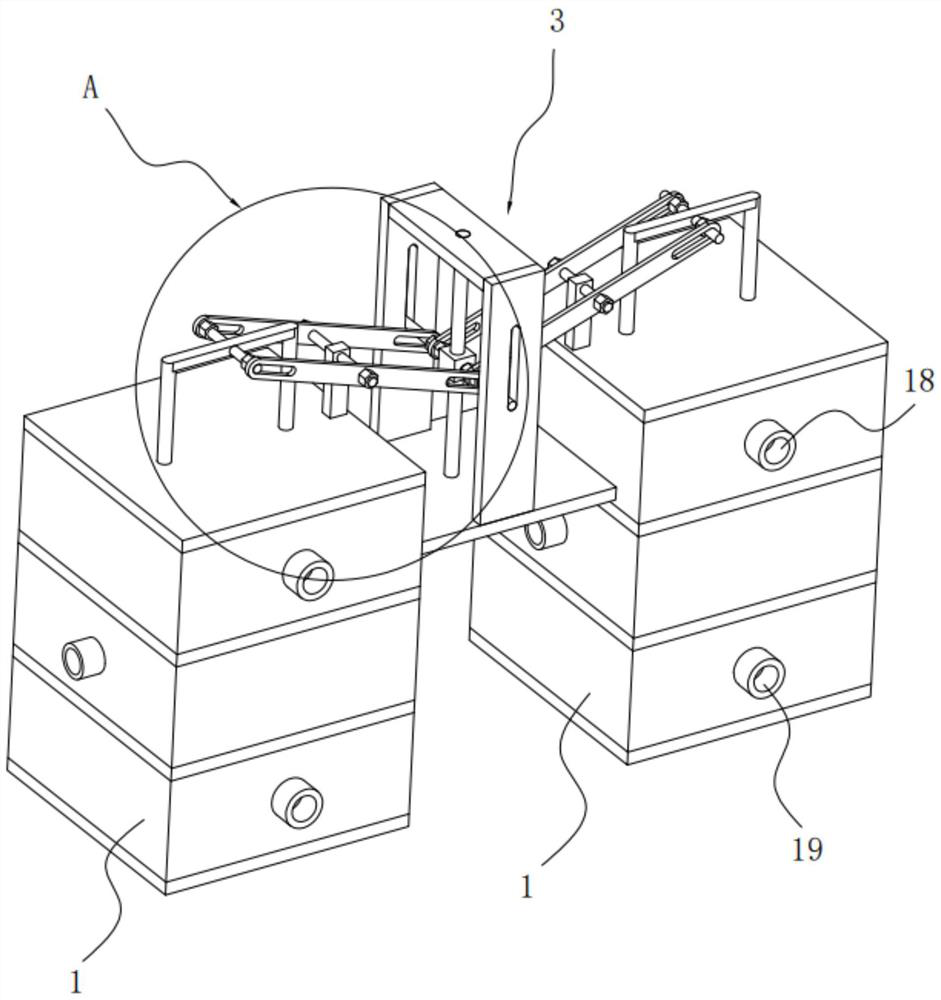
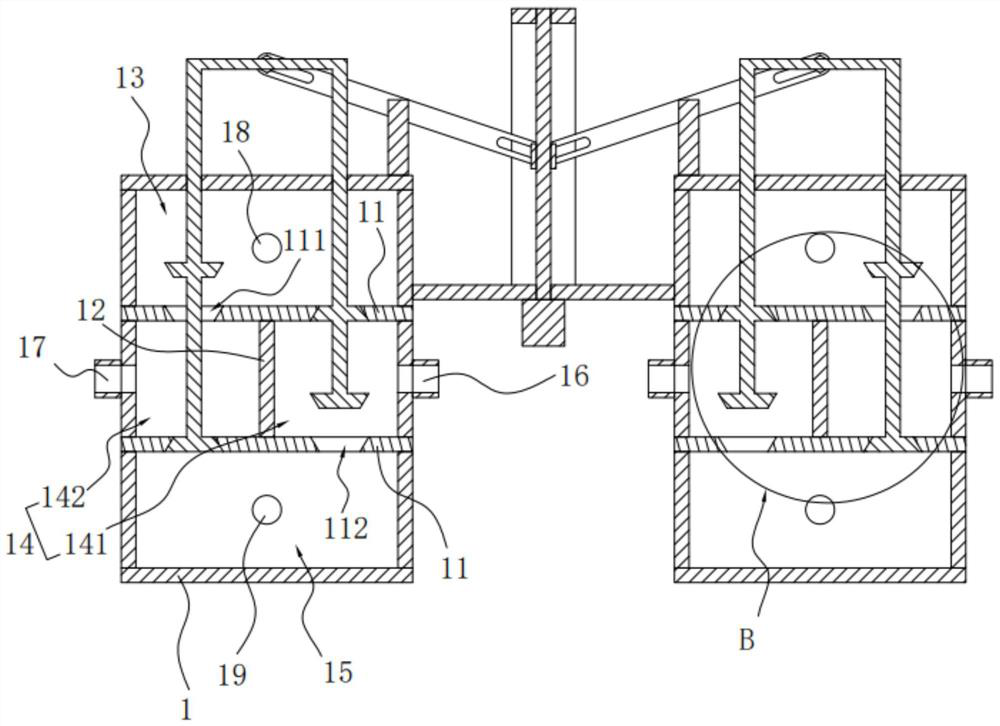
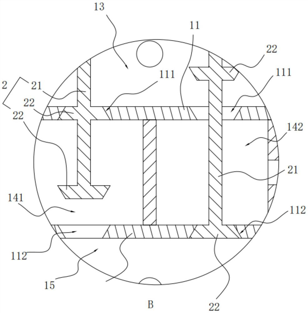
[0045] Embodiment 1: A synchronous reversing valve for an oxygen-enriched heating furnace, see the attached figure 1 , attached figure 2 And attached image 3 , including two valve bodies 1, a valve core 2 arranged in the two valve bodies 1, and a power mechanism 3 for driving the valve core 2 to move; specifically, the two valve bodies 1 have the same structure, and the inside of the valve body 1 is provided with a hollow Cavity, the valve body 1 is provided with two partition plates 11 fixedly connected to the inner wall of the valve body 1, and the two partition plates 11 are arranged in the vertical direction, thereby dividing the cavity in the valve body 1 from top to bottom. It is a fluid chamber 13, a switching chamber 14 and an exhaust gas chamber 15; in the middle of the switching chamber 14, a switching plate 12 is arranged between the two partition plates 11, and the switching plate 12 is fixedly connected with the partition plate 11 and the inner wall of the swit...

Embodiment 2

[0065] Embodiment two: a kind of oxygen-enriched heating furnace, see attached Figure 6 , which includes a furnace body 4, a gas pipe 6 for providing gas for the furnace body 4, an oxygen-enriched air pipe 5 for providing oxygen-enriched air for the furnace body 4, and two exhaust pipes for exhausting the exhaust gas in the furnace body 4. Air pipe 7, four regenerators 41 fixedly connected on the furnace body 4 and the reversing valve in the first embodiment; specifically; the gas pipe 6 and the oxygen-enriched air pipe 5 are connected with the two fluidic inlet pipes of the two valve bodies 1 respectively. 18 connection, the two tail gas pipes 7 are connected with the two tail gas discharge pipes 19 of the two valve bodies 1 respectively, and the four regenerators 41 are connected with the two first connecting pipes 16 and the two second connecting pipes of the two valve bodies 1 respectively.

[0066] Specifically, the two regenerators 41 connected with the two first connec...


PUM


Abstract

The invention discloses a synchronous reversing valve for an oxygen-enriched heating furnace, and relates to a fluid switching valve for the oxygen-enriched heating furnace. According to the key points of the technical scheme, the synchronous reversing valve comprises two valve bodies, valve elements and a power mechanism; each valve body is internally provided with two valve elements; the power mechanism is used for driving the four valve elements on the two valve bodies to synchronously act; two partition plates are arranged in each valve body and distributed in the vertical direction to divide each valve body into a fluid cavity, a switching cavity and a tail gas cavity from top to bottom; a switching plate is arranged between the two partition plates and divides the switching cavity into a first cavity body and a second cavity body; two valve inlet holes formed in each top partition plate are formed in the tops of the first cavity and the second cavity, and two valve outlet holes formed in each bottom partition plate are formed in the bottoms of the first cavity and the second cavity; and state switching of the two valve bodies is driven by the same power mechanism, so that good synchronization of state switching of the valve bodies can be kept.

Description

technical field [0001] The invention relates to a fluid switch valve for an oxygen-enriched heating furnace, more specifically, it relates to a synchronous reversing valve for an oxygen-enriched heating furnace. Background technique [0002] Oxygen-enriched combustion-supporting technology is an energy-saving combustion technology applied to industrial heating furnaces. It has the characteristics of increasing flame temperature, enhancing radiation heat transfer capacity, reducing exhaust emissions, and improving thermal efficiency; in oxygen-enriched heating furnaces, oxygen and air are mixed Then the oxygen-enriched air is formed, and the oxygen-enriched air is passed into the industrial heating furnace to promote the full combustion of the gas. [0003] In the prior art, in order to achieve a better effect, a regenerator is installed on the oxygen-enriched heating furnace, and through the reversing valve on the regenerator, the smoke-containing tail gas and air or gas are...

Claims


Application Information

Patent Timeline
Patent Type & Authority Applications(China)
IPC IPC(8): F16K11/10F16K27/02F16K31/44
CPCF16K11/10F16K27/0263F16K31/44
Inventor 张作帅
Owner 张作帅
Learn More