
Self-adaptive injection molding amount automatic injection molding opening sealing device for electromechanical injection mold

An injection mold, automatic closing technology, applied in applications, household components, household appliances, etc., can solve the problems of difficult control of injection volume and difficult control of opening and closing timing of exhaust holes.

Inactive Publication Date: 2021-07-23
东莞市社利机电科技有限公司
View PDF0 Cites 1 Cited by
  • Summary
  • Abstract
  • Description
  • Claims
  • Application Information

AI Technical Summary

Problems solved by technology

[0005] Aiming at the deficiencies of the prior art, the present invention provides a device for automatically closing the injection port of an electromechanical injection mold with an adaptive injection volume, which has the functions of automatically controlling the injection volume, automatically closing the vent hole after injection molding, and automatically separating the injection head from the mold. Advantages, it solves the problems that the injection volume is difficult to control, and the opening and closing timing of the vent hole is difficult to control.

Method used


Image

  • Self-adaptive injection molding amount automatic injection molding opening sealing device for electromechanical injection mold
  • Self-adaptive injection molding amount automatic injection molding opening sealing device for electromechanical injection mold
  • Self-adaptive injection molding amount automatic injection molding opening sealing device for electromechanical injection mold

Examples


Embodiment Construction

[0024] The following will clearly and completely describe the technical solutions in the embodiments of the present invention with reference to the accompanying drawings in the embodiments of the present invention. Obviously, the described embodiments are only some, not all, embodiments of the present invention. Based on the embodiments of the present invention, all other embodiments obtained by persons of ordinary skill in the art without making creative efforts belong to the protection scope of the present invention.

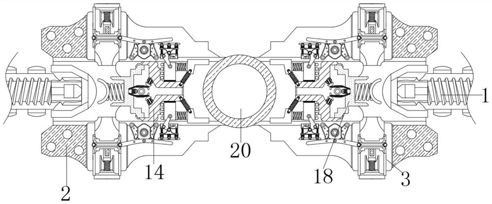
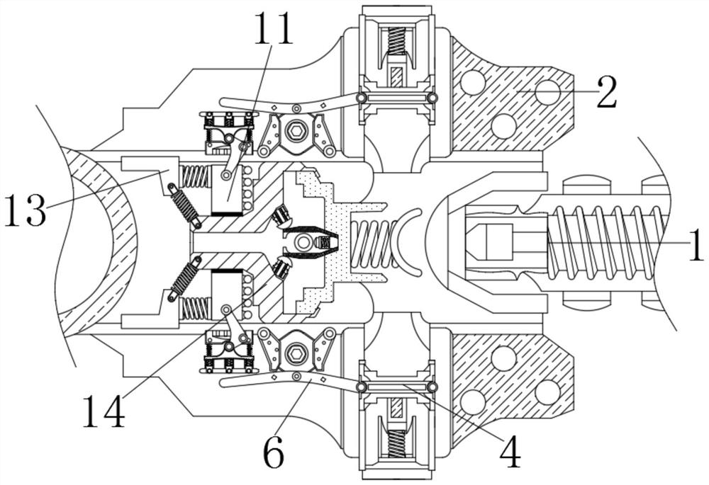
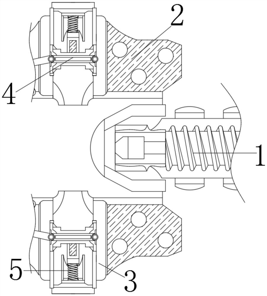
[0025] see Figure 1-5 , a device for automatically closing the injection port of an electromechanical injection mold with an adaptive injection volume, comprising an injection head 1, one end of the injection head 1 is movably connected to an injection pipe 2, and the surface of the injection pipe 2 is provided with a vent hole 3, the vent hole The inner wall of 3 is movably connected with a floating plate 4, the surface of the floating plate 4 is fixedly con...


PUM


Abstract

The invention relates to the technical field of mechanical and electromechanical equipment mold manufacturing, and discloses a self-adaptive injection molding amount automatic injection molding opening sealing device for an electromechanical injection mold. The self-adaptive injection molding amount automatic injection molding opening sealing device comprises an injection molding head, an injection molding pipe is movably connected with one end of the injection molding head, an exhaust hole is formed in the surface of the injection molding pipe, a floating plate is movably connected with the inner wall of the exhaust hole, an elastic seat is fixedly connected with the surface of the floating plate, a rotating rod is movably connected with the surface of the floating plate, a pressing plate is movably connected with the other end of the rotating rod, a flexible pipe is movably connected with the other side face of a lantern ring, and a push rod is movably connected with the other end of the flexible pipe. A one-way valve is movably connected with the other end of the push rod, a push plate is movably connected with the other end, away from the push rod, of the one-way valve, and an arc-shaped plate is fixedly connected to the other end of the push plate. The floating plate is pushed to move through molten plastic, the lantern ring is driven to extrude the flexible pipe, the push rod pushes the one-way valve to be closed, and the flexible pipe pushes the push plate, so that the arc-shaped plate pushes the injection molding head out of the injection molding pipe.

Description

technical field [0001] The invention relates to the technical field of mold manufacturing for mechanical and electrical equipment, in particular to a device for automatically closing the injection port of an electromechanical injection mold with an adaptive injection volume. Background technique [0002] Mechanical and electrical equipment generally refers to machinery, electrical appliances and electrical automation equipment. In construction, it refers to the collective name of machinery and pipeline equipment other than geotechnical, carpentry, steel bars, and muddy water. It is different from hardware and refers to finished products that can achieve certain functions. Machinery Electromechanical equipment is mostly manufactured through special molds, such as stamping molds, injection molds, etc. [0003] Electromechanical equipment needs to carry out injection molding of plastic components such as casings. During injection molding, too much injection volume will lead to ...

Claims


Application Information

Patent Timeline
Patent Type & Authority Applications(China)
IPC IPC(8): B29C45/28B29C45/34B29L31/34
CPCB29C45/2803B29C45/34B29C2045/2886B29L2031/3481
Inventor 刘权
Owner 东莞市社利机电科技有限公司
Learn More