New energy automobile power battery pack shell stamping device

A technology for power battery packs and new energy vehicles, applied in the direction of feeding devices, positioning devices, storage devices, etc., can solve problems such as mold damage, burrs, clamping and demoulding, and easy deformation, so as to prevent deviation and reduce burrs , the effect of preventing deformation

Inactive Publication Date: 2021-12-10
杭州巍枫减速机械有限公司
View PDF5 Cites 5 Cited by
  • Summary
  • Abstract
  • Description
  • Claims
  • Application Information

AI Technical Summary

Problems solved by technology

[0004] Based on this, it is necessary to address the above problems and propose a new energy vehicle power battery pack shell stamping device that can automatically remove the stamped new energy vehicle power battery pack shell and automatically apply lubricant to reduce burrs. The existing technology proposed in the background technology is easily deformed by clamping and demolding by other equipment, which easily leads to mold damage and burrs

Method used


Image

  • New energy automobile power battery pack shell stamping device
  • New energy automobile power battery pack shell stamping device
  • New energy automobile power battery pack shell stamping device

Examples


Embodiment 1

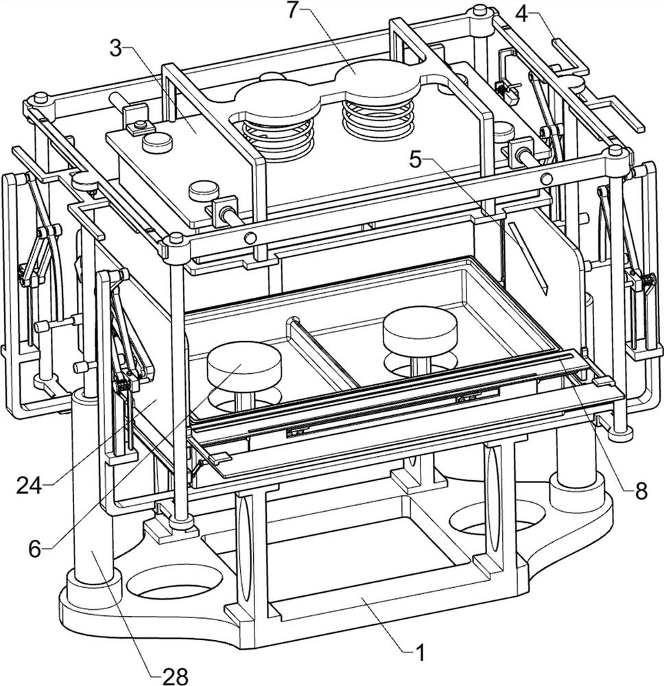
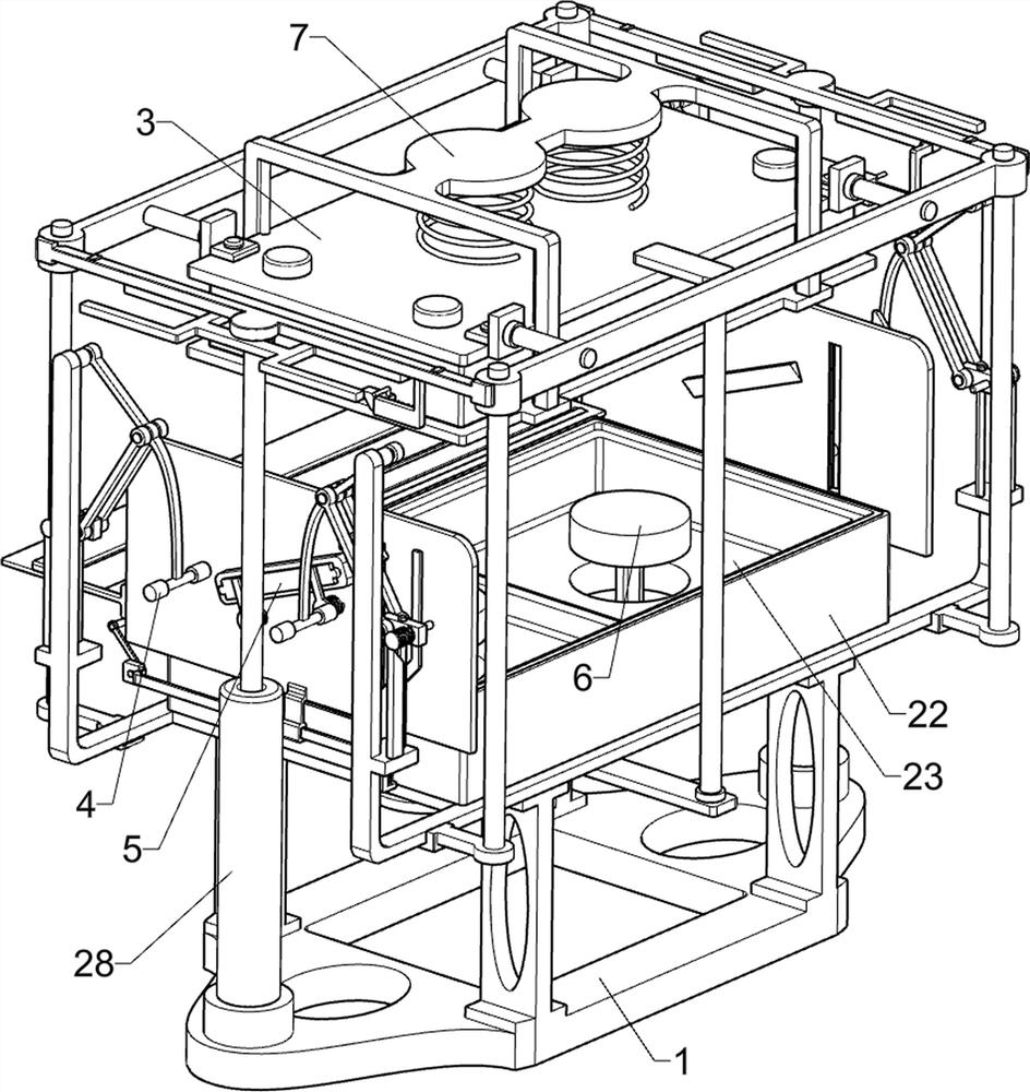
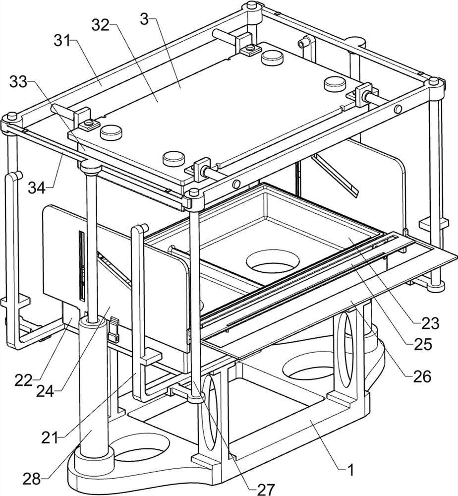
[0043] New energy vehicle power battery pack shell stamping device, such as figure 1 , figure 2 , image 3 , Figure 4 , Figure 5 , Image 6 with Figure 7 As shown, it includes a support base 1, a special-shaped support frame 21, a mold support frame 22, a lower mold frame 23, a slotted limit plate 24, a slotted support plate 25, a U-shaped support plate 26, a limit sleeve rod 27, and a cylinder 28. Lifting component 3 and stamping component 4, the top of the support base 1 is fixedly connected with a special-shaped support frame 21, the top of the special-shaped support frame 21 is fixed with a mold support frame 22, and the inside of the mold support frame 22 is fixed with a lower mold frame 23. The left and right sides of the support frame 22 are fixedly connected with a slotted stop plate 24, the front side of the mold support frame 22 is fixedly connected with a slotted support plate 25, and the slotted support plate 25 is fixedly connected with the slotted limit ...

Embodiment 2

[0048] On the basis of Example 1, such as Figure 8 , Figure 9 , Figure 10 , Figure 11 with Figure 12 As shown, it also includes a leftover material separation assembly 5, which is used to separate the leftover material of the steel plate. Rod 53, transmission wedge frame 54, wedge-shaped slant plate 55, return spring 56, sliding clamp block 57, reciprocating spring 58, L-shaped support frame 59, wedge-shaped push block 510, return spring 511 and return frame 512, slotted support The plate 25 is slidably connected with a baffle frame 51, the baffle frame 51 is used to temporarily block the leftovers of the steel plate, a pair of tension springs 52 are connected between the baffle frame 51 and the slotted support plate 25, and the baffle frame 51 rotates A pair of swinging rods 53 are connected in the same way, and a drive wedge frame 54 is slidingly connected under the slotted limit plate 24. The drive wedge frame 54 is located on the side where the two slotted limit p...

Embodiment 3

[0051] On the basis of Example 2, such as Figure 13 with Figure 14 As shown, the demoulding assembly 6 is also included, and the demoulding assembly 6 for demoulding the stamped power battery casing is arranged on the mold support frame 22. The demoulding assembly 6 includes a push-out frame 61, a T-shaped Frame 62, compression spring 63 and second push rod 64, a pair of push-out frames 61 for pushing out the punched power battery case are slidably connected on the mold support frame 22, and a T-shaped frame is fixedly connected between the two push-out frames 61. Frame 62, T-shaped frame 62 is positioned at below mold support frame 22, is connected with a pair of compression springs 63 for driving T-shaped frame 62 and its upper device to move downwards between T-shaped frame 62 and mold support frame 22, T-shaped frame 62 top is fixedly connected with a second push rod 64, the second push rod 64 is located at the rear side of the mold support frame 22, and the second push...


PUM


Abstract

The invention provides a new energy automobile power battery pack shell stamping device. The device comprises a supporting base, a special-shaped supporting frame, a mold supporting frame, a lower mold frame, grooving limiting plates and the like. The special-shaped supporting frame is fixedly connected to the top of the supporting base, the mold supporting frame is fixedly connected to the top of the special-shaped supporting frame, the lower mold frame is fixedly connected into the mold supporting frame, and the grooving limiting plates are fixedly connected to the left side and the right side of the mold supporting frame. In the stamping process, a push-out frame can move downwards, when stamping is completed, the push-out frame can move upwards and push out stamped new energy automobile power battery pack shells, an automatic demolding effect is achieved, other equipment can conveniently take out the new energy automobile power battery pack shells, the stamped new energy automobile power battery pack shells can be prevented from deforming, and the aim of automatically demolding the stamped new energy automobile power battery pack shells is achieved.

Description

technical field [0001] The invention relates to the field of new energy vehicles, in particular to a stamping device for a casing of a power battery pack of a new energy vehicle. Background technique [0002] Under the guidance of the rapid development of new energy vehicles in my country, electrification has become the main trend of global automobile development. Power batteries are power sources that provide power sources for tools. Power batteries mostly refer to electric vehicles, electric trains, electric bicycles, and golf carts. The battery that provides power, in which the power battery casing is the carrier of the battery module, plays a key role in the safe operation and protection of the battery module. [0003] In the process of processing the shell of the new energy vehicle power battery pack, the steel plate needs to be stamped to be processed into the shell of the new energy vehicle power battery pack. In the existing technology, the staff manually put the stee...

Claims


Application Information

Patent Timeline
Patent Type & Authority Applications(China)
IPC IPC(8): B21D22/02B21D37/18B21D37/10B21D37/12B21D45/02B21D43/00
CPCB21D22/02B21D37/18B21D37/10B21D37/12B21D45/02B21D43/003
Inventor 林利娜
Owner 杭州巍枫减速机械有限公司
Why Eureka
Try Eureka