A stamping equipment for panoramic sunroof beam mold

A technology of stamping equipment and panoramic sunroof, which is applied in the field of stamping equipment, can solve the problems of declining product competitiveness, increased production cost of sunroof beams, troubles, etc., to improve the stamping pressure and stamping speed, facilitate finishing and later maintenance, and complicate the mechanism structure Effect

Active Publication Date: 2020-07-24
天津希利汽车部品有限公司
View PDF6 Cites 0 Cited by
  • Summary
  • Abstract
  • Description
  • Claims
  • Application Information

AI Technical Summary

Problems solved by technology

There are many defects in this kind of production equipment. First of all, in the stamping process, there are slight differences in the stamping force generated in different stamping processes, which leads to the height and thickness of the beams produced are not exactly the same. If the beams with large errors are in the There will be a problem of mismatching with other accessories during installation; in addition, the form of the mold is fixed, and the radian, length and hardness of the beam have been set. If other types of skylight beams need to be replaced and re-adjusted, it is very It is troublesome, and the punching machine tool does not have precise positioning control and output, which is also an important reason for the poor quality of the product. The cost from the punching machine tool to different sets of molds is very high, so the production cost of the skylight beam will increase, leading to product competition How to solve the above problems, make the production of panoramic sunroof beams more smooth, efficient and accurate, and improve the working environment are the problems that need to be improved and solved

Method used


Image

  • A stamping equipment for panoramic sunroof beam mold
  • A stamping equipment for panoramic sunroof beam mold
  • A stamping equipment for panoramic sunroof beam mold

Examples


Embodiment Construction

[0039] The specific implementation manners of the present invention will be briefly described below in conjunction with the accompanying drawings.

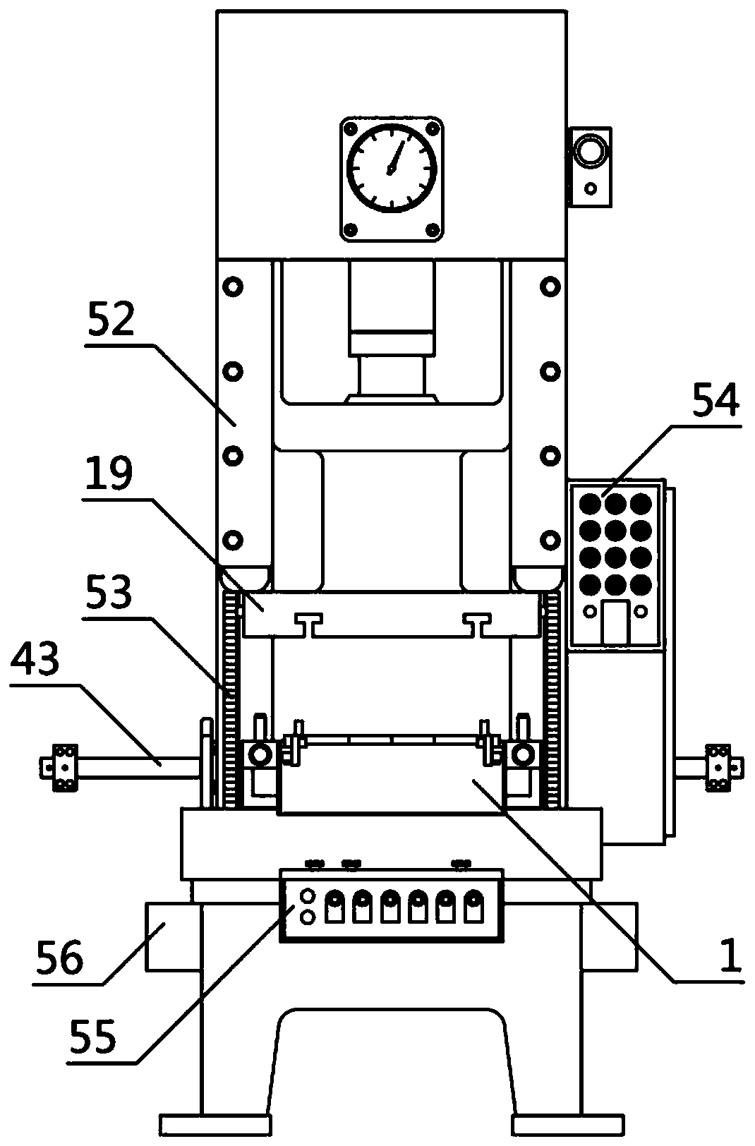
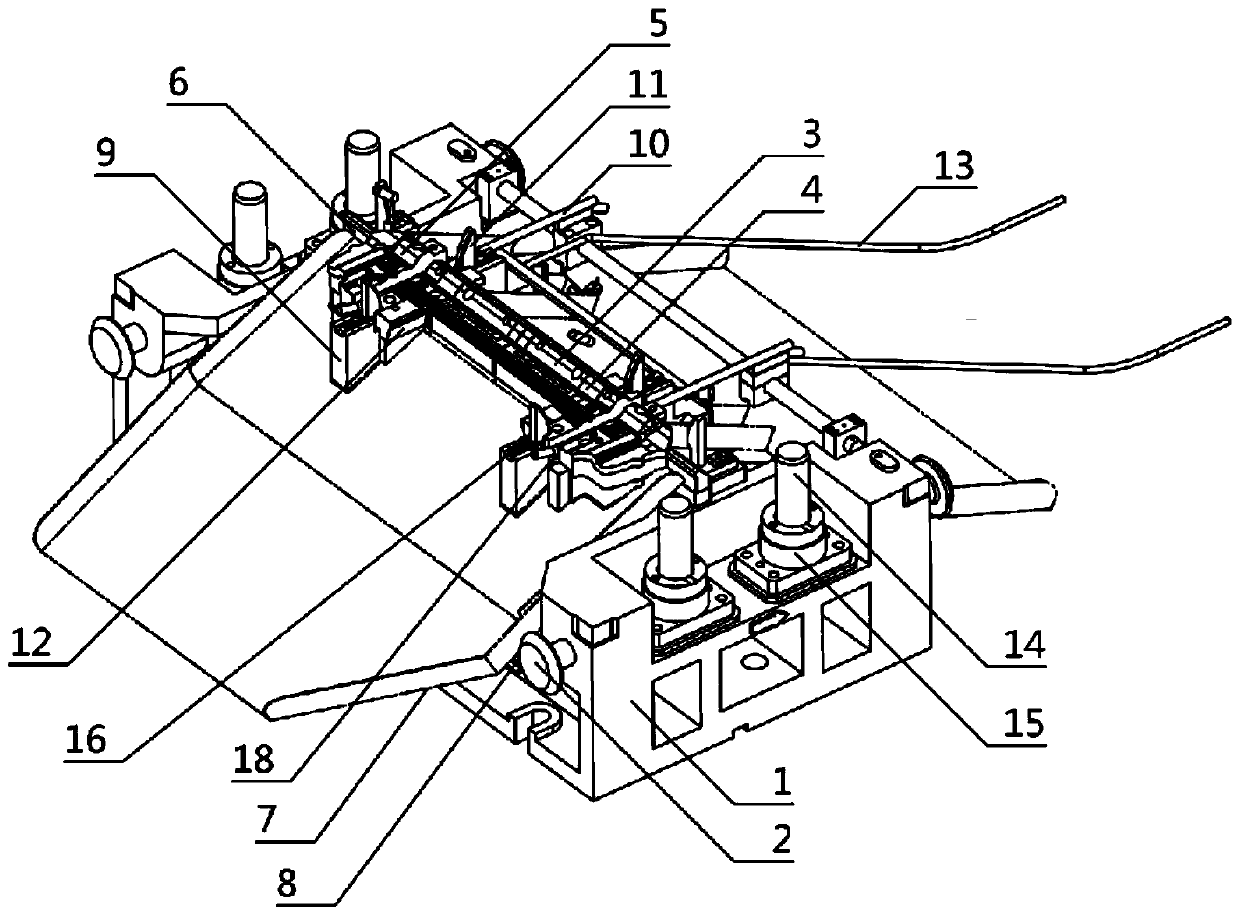
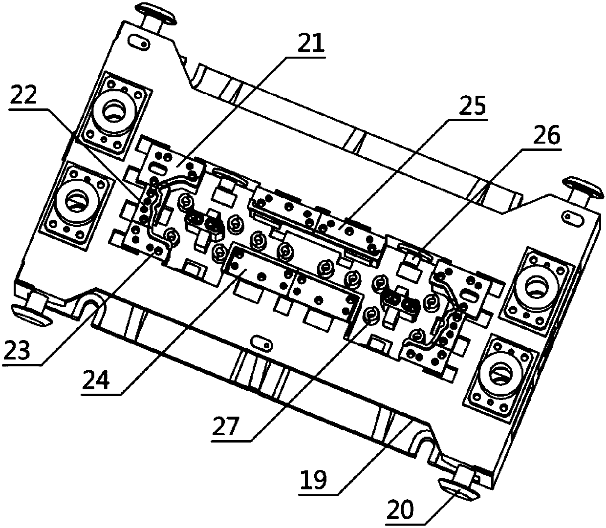
[0040] Such as figure 1 , figure 2 , image 3 , Figure 4 , Figure 5 , Figure 6 , Figure 7Shown is a stamping device for a panorama sunroof beam mold, which is characterized in that it includes a lower mold body 1, an upper mold body 19, a pressing core 28, a single air path system 32, a bracket 43 and a stamping device 52. The lower die body 1, the upper die body 19 and the pressing core 28 are all located inside the punching device 52, the lower die body 1 and the upper die body 19 are fixedly connected to the punching device 52, and the lower die body 1 is located The lower part of the upper die body 19, the lower die body 1 is movably connected with the upper die body 19, and the binder core 28 is positioned at the inside of the lower die body 1, and the binder core 28 and the lower die body 1 are fixed connected, t...


PUM


Abstract

The invention provides a panoramic sunroof cross beam die and a punching device thereof. The technical scheme is that the panoramic sunroof cross beam die comprises a lower die body, an upper die body, a pressing core, a single-air path system, a carrying rack and the punching device. According to the panoramic sunroof cross beam die and the punching device thereof, an upper die and a lower die cooperate to shape the pressing core, and output of an automobile sunroof cross beam is more accurate; the single-air path system is used for controlling the punching device, the device is more accurate, control of the punching device is more smooth, punching force and punching speed are increased, and processing quality is improved; the structure of an entire mechanism is complex, operation is easyand convenient, punching locating tracks on the punching device are gear type perpendicular locating devices, the upper die body can be driven to move up and down, lifting motion according to a travelling track is more standard, and an accurate locating function is achieved; and besides, the upper and lower dies cooperate to shape a die core, output of the automobile sunroof cross beam is more accurate, the aesthetic degree of a product is higher, input of processing raw materials and output of the product are facilitated, and working efficiency is improved.

Description

technical field [0001] The invention relates to the field of production and processing of automobile parts, in particular to a stamping device for a panorama sunroof beam mold. Background technique [0002] With the improvement of living standards, cars have become an indispensable means of transportation in people's lives. While people are pursuing beauty, they also put forward higher requirements for the comfort of driving. Many commercial SUVs and cars are equipped with sunroofs on the roofs. The sunroofs can effectively circulate the air in the car and increase fresh air. Entering the car will bring healthy and comfortable enjoyment to the car owner. At the same time, the car sunroof can also broaden the field of vision and make the people in the car feel more comfortable. Even if the existing cars have a panoramic sunroof, they are generally designed with beams, and the beams on the car are generally opaque structures, so it will affect the visual effect above, and the...

Claims


Application Information

Patent Timeline
Patent Type & Authority Patents(China)
IPC IPC(8): B21D22/02B21C51/00B21D37/10B21D45/00B21D45/08B21D37/12B21D43/20
Inventor 傅延权
Owner 天津希利汽车部品有限公司
Why Eureka
Try Eureka