
A film stamping device

A stamping device and film technology, applied to cleaning methods and appliances, chemical instruments and methods, cleaning methods using gas flow, etc., can solve problems such as film tearing, avoid tearing deformation, improve stamping efficiency, and facilitate cleaning Effect

Active Publication Date: 2020-09-22
江苏鑫易达新材料科技有限公司
View PDF5 Cites 0 Cited by
  • Summary
  • Abstract
  • Description
  • Claims
  • Application Information

AI Technical Summary

Problems solved by technology

[0004] In order to make up for the deficiencies of the prior art, the present invention proposes a film punching device, which can solve the problem that the film is easily torn during the stamping process, and improves the quality of the stamped film

Method used


Image

  • A film stamping device
  • A film stamping device
  • A film stamping device

Examples


Embodiment Construction

[0021] In order to make the technical means, creative features, goals and effects achieved by the present invention easy to understand, the present invention will be further described below in conjunction with specific embodiments.

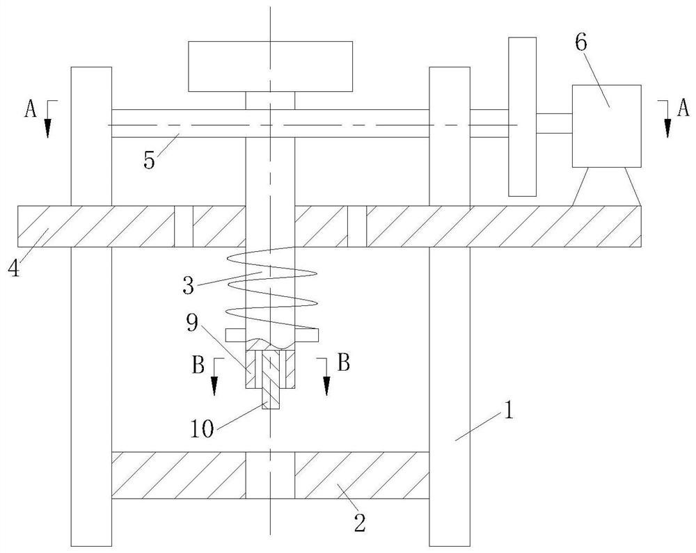
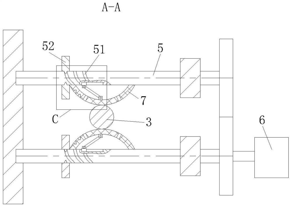
[0022] like Figure 1 to Figure 4 As shown, a film punching device according to the present invention includes a bracket 1, a substrate 2, a stamping rod 3, a support plate 4, a rotating shaft 5, a motor 6 and a controller, the substrate 2 is located at the bottom of the bracket 1, and the substrate 2 Punching holes are provided; the support plate 4 is located at the top of the bracket 1, a vertical plate is provided on one side of the support plate 4, and two support columns are provided on the other side; the bottom end of the stamping rod 3 passes through the support plate 4, and the stamping rod 3. The top end is fixed to the block, and two rotating shafts 5 are arranged symmetrically on both sides of the stamping rod 3; Hemispherical airbag ...


PUM


Abstract

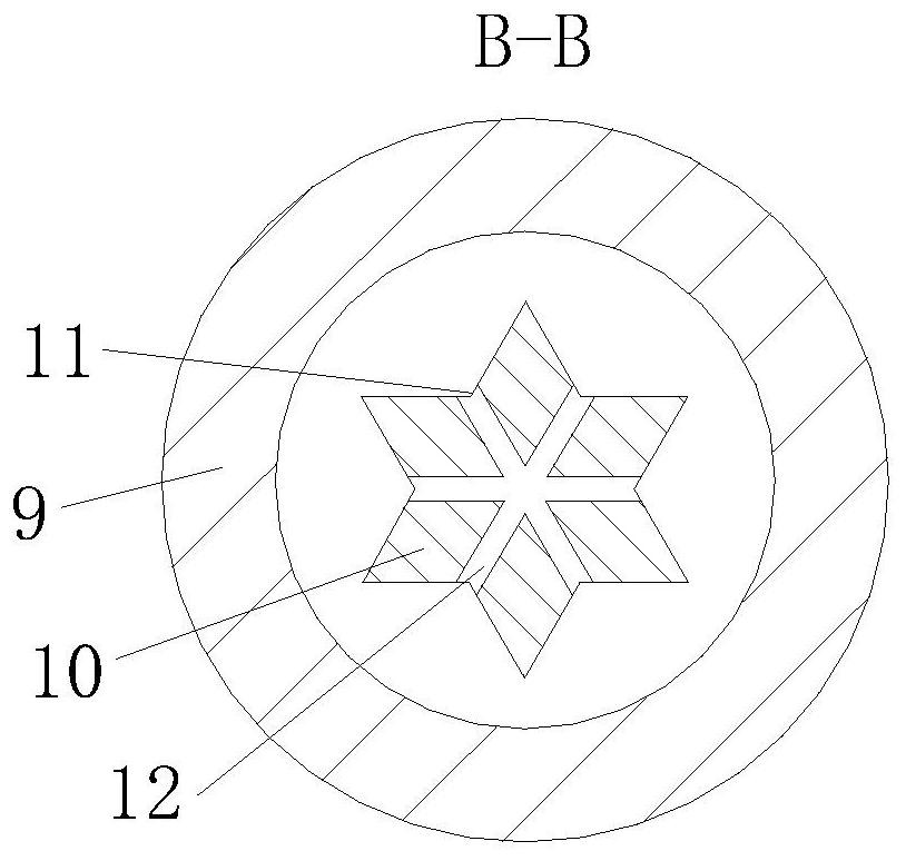
The invention belongs to the technical field of film processing, and specifically discloses a film stamping device. The film stamping device comprises a bracket, a base plate, a stamping rod, a supporting plate, a rotary shaft, a motor and a controller, wherein the base plate is positioned on the bottom of the bracket; a stamping hole is formed in the base plate; the supporting plate is positionedon the top of the bracket; a vertical plate is arranged at one side of the supporting plate; two supporting columns are arranged at the other side of the supporting plate; the bottom end of the stamping rod passes through the supporting plate, and the top end of the stamping rod is fixedly connected with a baffle block; the two sides of the stamping rod are symmetrically equipped with two rotaryshafts; ends of the rotary shafts are rotatably connected onto the vertical plate, and the other ends of the rotary shafts pass through the supporting columns and are fixedly connected with gears; semi-spherical gasbags are arranged at sides of the rotary shafts; and the two gears can be engaged, and one gear is driven by a motor. The film stamping device utilizes the semi-spherical gasbags to push the stamping rod to stamp a film back and forth; and a hexagonal cutter arranged at the bottom end of the stamping rod is matched with a ring-shaped cutter, so that tear deformation, caused by tension of the film, in a stamping process of the film, is avoided, and therefore, film stamping quality is improved.

Description

technical field [0001] The invention belongs to the technical field of film processing, in particular to a film stamping device. Background technique [0002] Films made of polyvinyl chloride, polyethylene, polypropylene, polystyrene, and other resins, used for packaging and as laminations. Plastic packaging and plastic packaging products account for an increasing share in the market, especially composite plastic flexible packaging, which has been widely used in food, medicine, chemical and other fields, among which food packaging accounts for the largest proportion, such as beverage packaging , quick-frozen food packaging, cooking food packaging, fast food packaging, etc., these products have brought great convenience to people's lives. [0003] The application of plastic films is extremely extensive and involves various fields. Therefore, the requirements for the shape of plastic films have also increased, including punching holes for plastic films. Existing punching equi...

Claims


Application Information

Patent Timeline
Patent Type & Authority Patents(China)
IPC IPC(8): B26F1/38B26F1/44B26D5/08B26D7/18B08B5/02
CPCB08B5/02B26D5/08B26D7/1854B26F1/38B26F1/44
Inventor 王顺夏敏月
Owner 江苏鑫易达新材料科技有限公司
Learn More