
Photo frame corner punching device

A photo frame and angle of attack technology, applied in metal processing equipment and other directions, can solve the problem of low processing efficiency of photo frames, and achieve the effects of reducing gas flow, reducing impulse and increasing impulse.

Pending Publication Date: 2021-07-13
佛山市三水长河实业有限公司
View PDF0 Cites 0 Cited by
  • Summary
  • Abstract
  • Description
  • Claims
  • Application Information

AI Technical Summary

Problems solved by technology

[0003] The purpose of the present invention is to propose a photo frame punching angle device to solve the technical problem of low photo frame processing efficiency due to the fixed output power of the existing punching machine

Method used


Image

  • Photo frame corner punching device
  • Photo frame corner punching device
  • Photo frame corner punching device

Examples


Embodiment Construction

[0024] Embodiments of the present invention are described in detail below, examples of which are shown in the drawings, wherein the same or similar reference numerals designate the same or similar elements or elements having the same or similar functions throughout. The embodiments described below by referring to the figures are exemplary only for explaining the present invention and should not be construed as limiting the present invention.

[0025] In describing the present invention, it should be understood that the terms "longitudinal", "transverse", "upper", "lower", "front", "rear", "left", "right", "vertical", " The orientations or positional relationships indicated by "horizontal", "top", "bottom", "inner", "outer", etc. are based on the orientations or positional relationships shown in the drawings, and are only for the convenience of describing the present invention and simplifying the description, rather than Nothing indicating or implying that a referenced device o...


PUM


Abstract

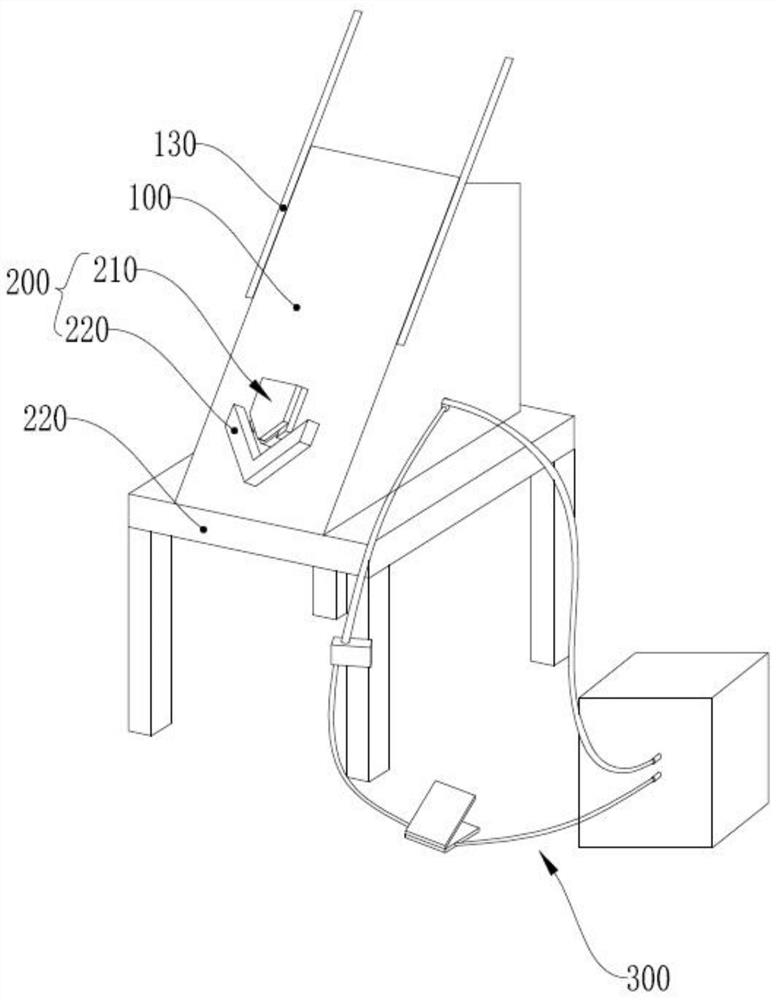
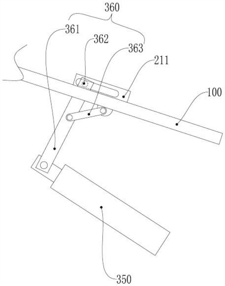
The invention discloses a photo frame corner punching device, and relates to the technical field of photo frame processing. The photo frame corner punching device comprises a photo frame backup plate, a corner punching assembly and a driving assembly; the corner punching assembly comprises a punching head and a supporting base, the punching head and the supporting base are arranged on a panel of the photo frame backup plate, and the output end of the punching head outputs towards the supporting base; the driving assembly comprises an air source, a pneumatic valve, a foot switch, an adjusting air valve and a driving air cylinder; the input end of the pneumatic valve communicates with the air source, and the output end of the pneumatic valve communicates with the input end of the driving air cylinder; the output end of the driving cylinder is in transmission connection with the output end of the punching head; and the input end of the foot switch communicates with the air source, the output end of the foot switch communicates with the input end of the adjusting air valve, and the output end of the adjusting air valve communicates with an actuator of the pneumatic valve. The punching force of the punching head is adjustable, the situations that an aluminum strip is crushed due to too large punching force and a convex buckle cannot be pressed on the aluminum strip due to too small punching force can be effectively reduced, and the processing efficiency of a photo frame is improved.

Description

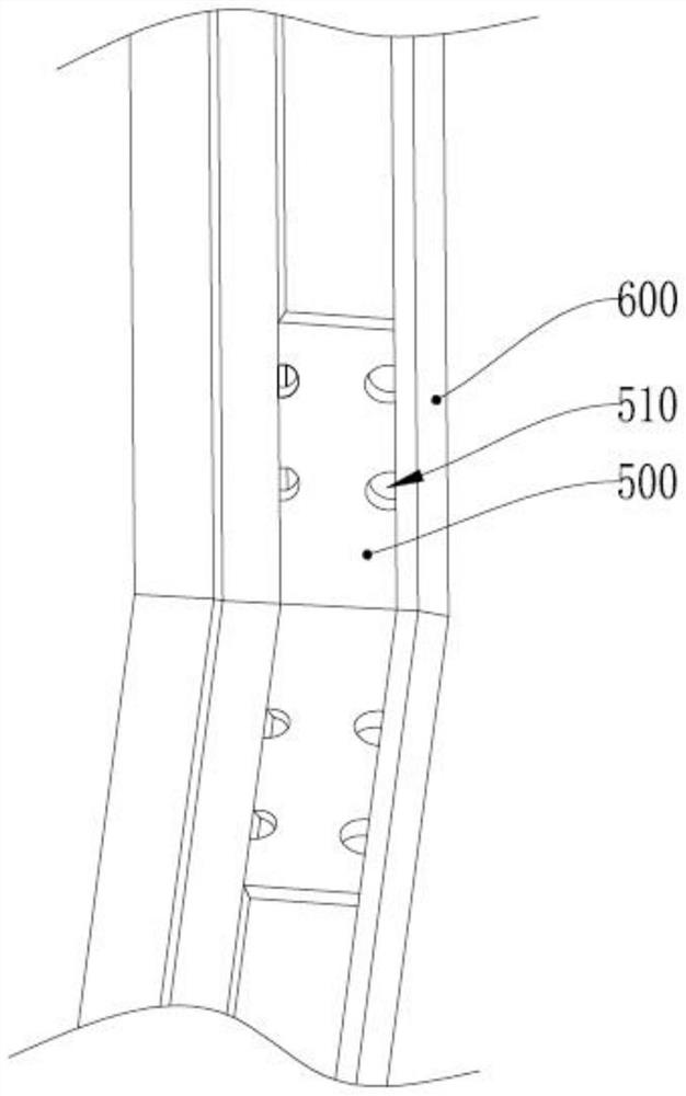
technical field [0001] The invention relates to the technical field of photo frame processing, in particular to a photo frame angle device. Background technique [0002] Existing aluminum alloy photo frames are assembled by multiple aluminum strips, such as figure 1 As shown, two aluminum strips 600 are connected with each other by means of a right-angle angle bracket 500 to form a right-angle frame corner, wherein buckle holes 510 are respectively provided on both sides of the right-angle angle bracket, and a convex buckle is pressed out on the aluminum strip by a punching machine Cooperate with the buckle hole 510 to realize the fixing of the aluminum bar 600 and the corner bracket 500 . However, the output power of existing stamping machines is often fixed, and it is easy to occur that the stamping force is too large and the aluminum strip is crushed, or the stamping force is too small to press the protruding buttons on the aluminum strip, which will cause the photo fram...

Claims


Application Information

Patent Timeline
IPC IPC(8): B21D39/00B21D53/74
CPCB21D39/00B21D53/745
Inventor 赖舜青李勇泉林有棠
Owner 佛山市三水长河实业有限公司
Learn More