[0022] In order to have a further understanding of the purpose, structure, features, and functions of the present invention, the following detailed descriptions are given in conjunction with the embodiments.
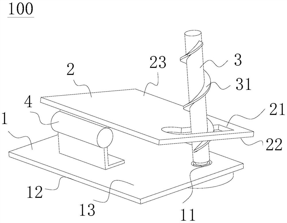
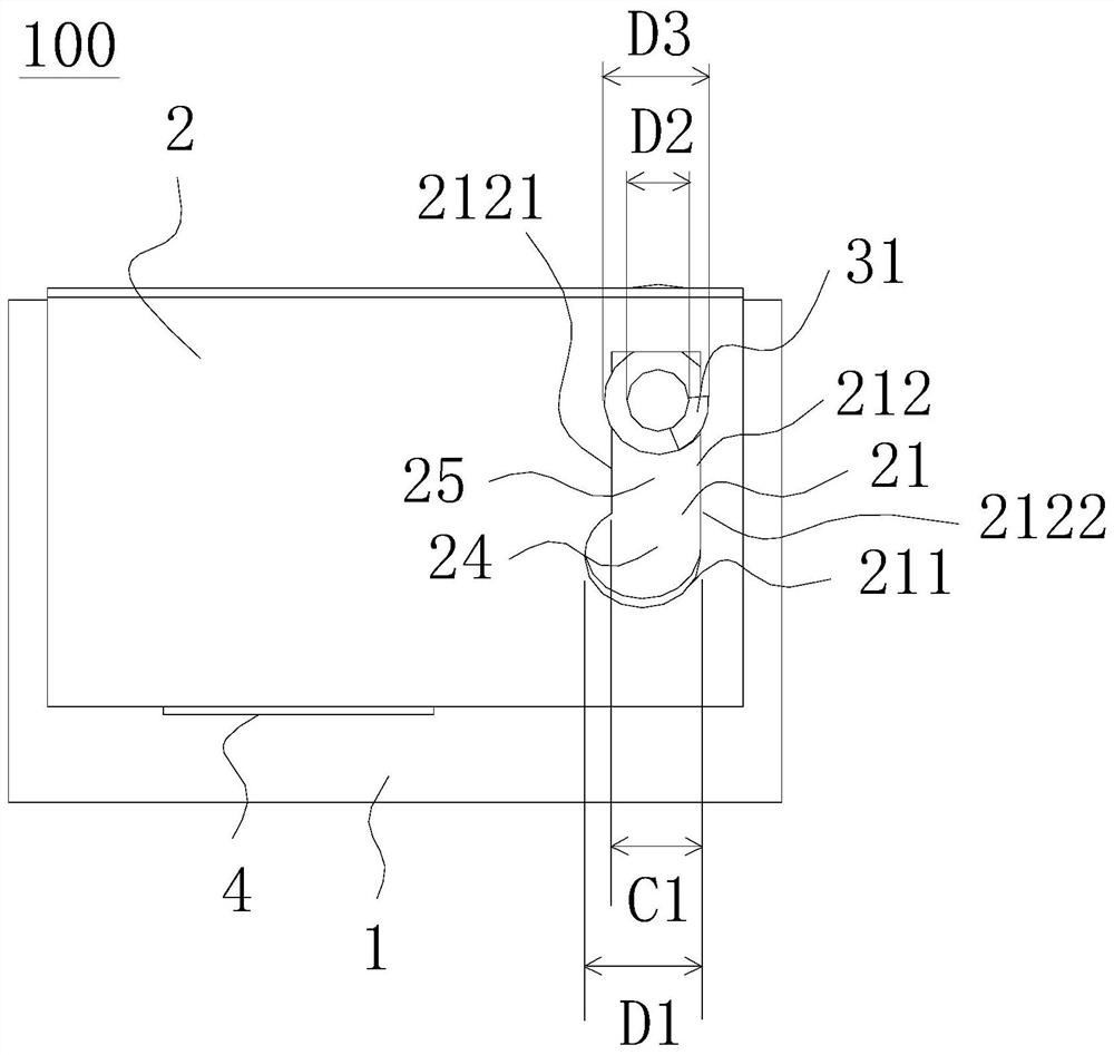
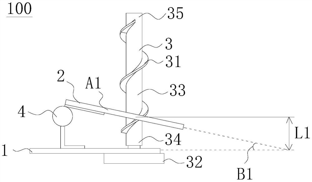
[0023] Please refer to Figure 1 to Figure 6 , figure 1 It is a schematic diagram of a three-dimensional structure of a base with an adjustable inclination angle according to an embodiment of the present invention, figure 2 It is a schematic top view of a base with an adjustable inclination angle according to an embodiment of the present invention, image 3 It is a schematic front view of the base with adjustable inclination angle in the first position according to an embodiment of the present invention, Figure 4 It is a schematic front view of the base with adjustable inclination angle in the second position according to an embodiment of the present invention, Figure 5 It is a schematic diagram of projecting an image when the projection device is in the first position according to an embodiment of the present invention, Image 6 It is a schematic diagram of projecting an image when the projection device is in the second position according to an embodiment of the present invention.
[0024] A base 100 with an adjustable tilt angle provided by an embodiment of the present invention is applied to a projection device 101, and the projection device 101 has a projection body 102 (see Figure 5 ), the base 100 with adjustable inclination angle includes a fixed plate 1, a rotating plate 2 and an adjustment member 3, the rotating plate 2 is used for fixedly connecting the projection body 102 and is pivotally connected to the fixed plate 1, the adjustment member 3 includes a spiral track 31, and the adjustment member 3 The spiral tracks 31 are respectively penetrated through the fixed plate 1 and the rotating plate 2 and interfere with the rotating plate 2 . When in use, the adjusting member 3 is rotated so that the spiral track 31 drives the rotating plate 2 and the projection body 102 to rotate through the interference, so as to adjust the angle between the rotating plate 2 and the projection body 102 relative to the fixed plate 1 , thereby adjusting the inclination of the projection device 101 , to change the position and/or angle of the image projected by the projection device 101 . In this way, the tilt angle of the base can be adjusted by simply rotating the adjusting member 3 and the image projection position and/or the projection angle of the projection device 101 can be changed.
[0025] Next, the structure and positional relationship of the fixed plate 1 , the rotating plate 2 , the adjustment member 3 and the projection body 102 will be described in detail as follows.
[0026] like figure 1 As shown, the fixing plate 1 has a first opening 11 , a first surface 12 and a second surface 13 , the first surface 12 is opposite to the second surface 13 , and the first opening 11 penetrates through the first surface 12 and the second surface 13 . In specific implementation, the fixing plate 1 is the bottom of the projection device 101 , and the fixing plate 1 is exposed on the projection body 102 , which can be placed on the operating platform, depending on the actual situation.
[0027] like figure 1 and figure 2 As shown, the rotating plate 2 has a second opening 21 , a third surface 22 and a fourth surface 23 , the third surface 22 is opposite to the fourth surface 23 , and the second opening 21 penetrates the third surface 22 and the fourth surface 23 . The second opening 21 includes a third opening 25 and a fourth opening 24 . In this embodiment, the fourth opening 24 is a circular opening 211 , the third opening 25 is an elongated opening 212 , and the circular opening 211 is communicated with the elongated opening 212 . The elongated opening 212 has a first side 2121 and a second side 2122, the first side 2121 is opposite to the second side 2122, and both the first side 2121 and the second side 2122 are connected to the circular opening 211. Side 2121 is parallel to second side 2122. The circular opening 211 has a first inner diameter D1, and the relative distance between the first side 2121 and the second side 2122 of the elongated opening 212 is the first width C1.
[0028] like figure 1 As shown, in this embodiment, the base 100 with adjustable inclination angle further includes a bearing 4, the bearing 4 is arranged on the second surface 12 of the fixed plate 1, the rotating plate 2 is pivotally connected to the bearing 4, and the rotating plate 2 is relative to the fixed plate through the bearing 4 1 rotation, the pivot connection between the rotating plate 2 and the fixed plate 1 is not limited to this, for example, the rotating plate 2 and the fixed plate 1 are connected by a torsion spring. When adjusting the inclination angle, it is found that a large force is required to rotate the adjusting member 3, it is known that the angle between the rotating plate 2 and the fixed plate 1 is about to reach the minimum or maximum value, which is convenient for the user to judge.
[0029] like image 3 and Figure 4As shown, the adjusting member 3 has a spiral track 31, a grip portion 32, a rotating shaft portion 33, a first end 34 and a second end 35, the first end 34 is opposite to the second end 35, and the first end 34 is close to the fixing plate 1, The second end 35 is far away from the fixing plate 1 . When the base 100 is assembled with the projection body 102 , the second end 35 is inserted into the projection body 102 . At the end 34 , the spiral track is arranged on the rotating shaft portion 33 . The shaft portion 33 has a first outer diameter D2, and the spiral track 31 has a second outer diameter D3. Rotate the grip portion 32 in the direction of the first plane to rotate the shaft portion 33, so that the spiral track 31 rotates along with it, so as to drive the rotating plate 2 to rotate relative to the fixed plate 1 in the direction of the second plane. The direction of the first plane and the second plane The directions are different. In actual operation, the first plane direction may be perpendicular to the second plane direction, and the first plane direction is, for example, the x-y plane direction; the second plane direction is, for example, the x-z plane direction.
[0030] In the embodiment of the present invention, refer to figure 1 , figure 2 and Figure 5 As shown, the inner diameter of the circular opening 211 corresponds to the outer diameter of the spiral track 31, and the first inner diameter D1 of the circular opening 211 is not less than the second outer diameter D3 of the spiral track 31, so that the adjusting member 3 can smoothly pass through the circular opening during assembly. Opening 211. The first width C1 is not smaller than the first outer diameter D2 of the rotating shaft portion 33 , the first width C1 is smaller than the second outer diameter D3 of the spiral track 31 , the width of the elongated opening 212 corresponds to the diameter of the rotating shaft portion 33 , and the elongated opening 212 The width is between the diameter of the shaft portion 33 and the outer diameter of the spiral track 31, so that the adjusting member 3 passing through the circular opening 211 can smoothly move from the circular opening 211 to the elongated opening 212 and make the spiral track 31 Interferes with the side of the elongated opening 212 , and drives the rotating plate 2 and the projection body 102 to rotate relative to the fixed plate 1 through the interference between the spiral track 31 and the side of the elongated opening 212 when the adjusting member 3 is subsequently rotated. . In actual operation, the fourth opening 24 may also be an opening of other shapes, such as a quadrangle, a pentagon, etc., as long as the adjusting member 3 can pass through the fourth opening 24 smoothly.
[0031] The adjusting member 3 passes through the first opening 11 and the second opening 21 , and the rotating adjusting member 3 causes the spiral track 31 to drive the rotating plate 2 to rotate relative to the fixed plate 1 through the interference with the second opening 21 . In the specific implementation, the screw track 31 is a large screw thread, the large screw thread is protruding on the rotating shaft portion 33, and the large screw thread drives the rotating plate 2 to achieve the effect of transferring the torque direction, so that the rotating plate 2 rotates relative to the fixed plate 1 to adjust the rotating plate 2. The angle relative to the fixed plate 1.
[0032] Preferably, the rotating shaft portion 33 passes through the first opening 11 and the second opening 21 , the rotating grip portion 32 rotates the rotating shaft portion 33 , and the rotating shaft portion 33 drives the spiral track 31 to interfere with the second opening 21 to drive the rotating plate 2 relative to the fixed plate 1 turn. Specifically, the spiral track 31 provided on the rotating shaft portion 33 is rotatable, the spiral track 31 rotates with the rotating shaft portion 33 , and the user rotates the grip portion 32 to make the rotating shaft portion 33 rotate along with the rotating spiral track 31 and the second opening 21 . Interference can achieve the effect of transferring the torque direction, so that the rotating plate 2 rotates relative to the fixed plate 1 to adjust the angle between the rotating plate 2 and the fixed plate 1 .
[0033] Preferably, the spiral track 31 is disposed in the elongated opening 212 in a restricted rotation, and the rotating grip portion 32 makes the spiral track 31 push the first side 2121 and the second side 2122 in turn to drive the rotating plate 2 to rotate relative to the fixed plate 1 . Specifically, the spiral track 31 provided on the rotating shaft portion 33 is rotatable, the spiral track 31 rotates with the rotating shaft portion 33 , the user rotates the grip portion 32 to make the rotating shaft portion 33 follow the rotation, and the rotating spiral track 31 pushes the elongated opening The first side 2121 and the second side 2122 of the 212, the helical track 31 is a large thread, and the large thread pushes the first side 2121 and the second side 2122 of the elongated opening 212 in turn to drive the rotating plate 2 to rotate relative to the fixed plate 1, The angle between the rotating plate 2 and the fixed plate 1 can be adjusted.
[0034] In the embodiment of the present invention, refer to Figure 1 to Figure 4 As shown in the figure, when adjusting the inclination, the position where the rotating adjusting member 3 interferes with the rotating plate 2 and the helical track 31 is from the first position A1 to the second position A2. At the first position A1, the rotating plate 2 has a first relative to the fixed plate 1 The included angle B1, at the second position A2, the rotating plate 2 has a second included angle B2 relative to the fixed plate 1, and the first included angle B1 is different from the second included angle B2. In the specific implementation, the adjusting member 3 passes through the first opening 11 and the second opening 21, and the adjusting member 3 is rotated to make the spiral track 31 interfere with the second opening 21 to drive the rotating plate 2 to rotate relative to the fixed plate 1, and the spiral track 31 is large. The large screw thread is protruding on the rotating shaft portion 33, and the large screw thread drives the rotating plate 2 to achieve the effect of transferring the torque direction, so that the interference between the rotating plate 2 and the spiral track 31 is from the first position A1 of the spiral track 31 to the spiral track 31. The second position A2. In this embodiment, the first position A1 is close to the fixed plate 1, and the second position A2 is far away from the fixed plate 1. When the spiral track 31 drives the rotating plate 2 to move from the first position A1 to the second position A2, the rotating plate 2 is relatively fixed at this time. The included angle of the plate 1 gradually increases from the first included angle B1 to the second included angle B2, and the first included angle B1 is smaller than the second included angle B2; when the spiral track 31 drives the rotating plate 2 to move from the second position A2 to the first included angle At the position A1, the angle between the rotating plate 2 and the fixed plate 1 gradually decreases from the first angle B1 to the second angle B2, and the first angle B1 is greater than the second angle B2.
[0035] In the embodiment of the present invention, refer to Figure 1 to Figure 4 As shown, the rotating shaft portion 33 passes through the first opening 11 and the second opening 21, the rotating grip portion 32 rotates the rotating shaft portion 33, and the rotating shaft portion 33 drives the spiral track 31 to interfere with the second opening 21 to drive the rotating plate 2 relative to the fixed plate 1 turn. The spiral track 31 provided on the rotating shaft portion 33 is rotatable, the spiral track 31 rotates along with the rotating shaft portion 33, the user rotates the grip portion 32 to make the rotating shaft portion 33 follow the rotation, and the rotating spiral track 31 interferes with the second opening 21 to make the rotating plate 2. The position that interferes with the spiral track 31 is moved from the first position A1 to the second position A2. In this embodiment, the first position A1 is close to the fixed plate 1, and the second position A2 is far away from the fixed plate 1. When the spiral track 31 drives the rotating plate 2 to move from the first position A1 to the second position A2, the rotating plate 2 is relatively fixed at this time. The included angle of the plate 1 gradually increases from the first included angle B1 to the second included angle B2, and the first included angle B1 is smaller than the second included angle B2; when the spiral track 31 drives the rotating plate 2 to move from the second position A2 to the first included angle At the position A1, the angle between the rotating plate 2 and the fixed plate 1 gradually decreases from the first angle B1 to the second angle B2, and the first angle B1 is greater than the second angle B2.
[0036] In the embodiment of the present invention, refer to Figure 1 to Figure 4 As shown, rotating the holding portion 32 makes the spiral track 31 push the first side 2121 and the second side 2122 in turn to drive the rotating plate 2 to rotate relative to the fixed plate 1, the spiral track 31 provided on the rotating shaft portion 33 can rotate, and the spiral track 31 follows As the shaft portion 33 rotates, the user rotates the grip portion 32 so that the shaft portion 33 rotates along with it, and the rotating spiral track 31 pushes the first side 2121 and the second side 2122 of the elongated opening 212 in turn. The spiral track 31 is a large thread, The large thread pushes the first side 2121 and the second side 2122 of the elongated opening 212 in turn so as to drive the position where the rotating plate 2 interferes with the spiral track 31 to move from the first position A1 to the second position A2 of the spiral track 31 . In this embodiment, the first position A1 is close to the fixed plate 1, and the second position A2 is far away from the fixed plate 1. When the spiral track 31 drives the rotating plate 2 to move from the first position A1 to the second position A2, the rotating plate 2 is relatively fixed at this time. The included angle of the plate 1 gradually increases from the first included angle B1 to the second included angle B2, and the first included angle B1 is smaller than the second included angle B2; when the spiral track 31 drives the rotating plate 2 to move from the second position A2 to the first included angle At the position A1, the angle between the rotating plate 2 and the fixed plate 1 gradually decreases from the first angle B1 to the second angle B2, and the first angle B1 is greater than the second angle B2.
[0037] refer to Figure 1 to Figure 4 As shown, rotating the adjusting member 3 makes the spiral track 31 drive the rotating plate 2 to move from the first end 34 to the second end 35, and the angle between the rotating plate 2 and the fixed plate 1 increases; The plate 2 moves from the second end 35 to the first end 34 , and the angle between the rotating plate 2 and the fixed plate 1 decreases. In specific implementation, the user rotates the grip portion 32 to make the shaft portion 33 rotate along with it, and the rotating spiral track 31 pushes the first side 2121 and the second side 2122 of the elongated opening 212 in turn. The thread alternately pushes the first side 2121 and the second side 2122 of the elongated opening 212 to drive the rotating plate 2 to move from the first end 34 to the second end 35, and the angle between the rotating plate 2 and the fixed plate 1 gradually increases; The user rotates the grip portion 32 in the opposite direction so that the shaft portion 33 rotates along with it, the rotating spiral track 31 pushes the first side 2121 and the second side 2122 of the elongated opening 212 in turn, the spiral track 31 is a large screw, and the large screw pushes in turn The first side 2121 and the second side 2122 of the elongated opening 212 are used to drive the rotating plate 2 to move from the second end 35 to the first end 34 , and the angle between the rotating plate 2 and the fixed plate 1 gradually decreases.
[0038] refer to Figure 1 to Figure 4 As shown, at the first position A1, the distance from the first position A1 to the fixing plate 1 along the length direction of the adjusting member 3 is the first length L1, and at the second position A2, the distance from the first position A1 along the length direction of the adjusting member 3 is the first length L1. The distance from the two positions A2 to the fixing plate 1 is the second length L2, and the first length L1 and the second length L2 are not equal; when the first length L1 is greater than the second length L2, the first included angle B1 is greater than the second included angle B2 ; When the first length L1 is smaller than the second length L2, the first included angle B1 is smaller than the second included angle B2. Specifically, the user rotates the grip portion 32 so that the shaft portion 33 rotates along with it, and the rotating spiral track 31 pushes the first side 2121 and the second side 2122 of the elongated opening 212 in turn. The spiral track 31 is a large thread, a large thread Push the first side 2121 and the second side 2122 of the elongated opening 212 in turn to drive the rotating plate 2 to move from the first position A1 to the second position A2, and from the first position A1 to the fixed plate along the length direction of the adjusting member 3 The distance of 1 is from the first length L1 to the second length L2. When the first position A1 is close to the fixed plate 1 and the second position A2 is far away from the fixed plate 1, the first length L1 is less than the second length L2; when the first position A1 is far away from the fixed plate 1 and the second position A2 is close to the fixed plate 1, The first length L1 is greater than the second length L2.
[0039] refer to Figure 5 and Image 6 As shown, the fixed plate 1 is placed on the operation platform 5, and when the rotating plate 2 interferes with the first position A1 of the spiral track 31, the projection body 102 projects an image with a first projection angle E1 relative to the operation platform 5. When interfering with the second position A2 of the spiral track 31, the projection body 102 projects an image with a second projection angle E2 relative to the operation platform 5, and the first projection angle E1 is different from the second projection angle E2. Specifically, the user rotates the adjusting member 3 to move the position where the rotating plate 2 interferes with the helical track 31 from the first position A1 to the second position A2, and the direction of the projected image from the projection body 102 changes from the first direction 1011 to the second direction 1012 , the angle between the direction of the projection body 102 to project the image relative to the operation platform 5 changes from the first projection angle E1 to the second projection angle E2. When the angle between the plate 2 and the fixing plate 1 changes, the angle at which the projection body 102 projects the image also changes, so that the angle at which the projection body 102 projects the image can be changed by operating the knob.
[0040] The present invention also proposes a projection device 101 comprising a projection body 102 and the above-mentioned base 100 with adjustable inclination angle.
[0041]To sum up, the base with an adjustable inclination angle and the projection device provided by the present invention, the base with an adjustable inclination angle includes a fixed plate, a rotating plate and an adjustment member, the rotating plate is pivotally connected to the fixed plate, and the adjustment member includes a spiral track, and the spiral track is arranged As for the adjustment piece, the adjustment piece is respectively penetrated on the fixed plate and the rotating plate. The rotating adjustment piece makes the spiral track drive the rotating plate to rotate relative to the fixed plate, and the angle between the rotating plate and the fixed plate is adjusted to adjust the inclination of the projection device. The rotating plate is from the first position of the spiral track to the second position of the spiral track, and the included angle of the rotating plate relative to the fixed plate is from the first included angle to the second included angle, and the first included angle is different from the second included angle. The tilt angle of the base can be adjusted and the projection angle of the image of the projection device can be changed by simply rotating the adjusting member.
[0042] Although the present invention is described with reference to the accompanying drawings, the embodiments disclosed in the accompanying drawings are intended to illustrate the preferred embodiments of the present invention, and should not be construed as a limitation of the present invention. In order to clearly describe the required components, the scale in the schematic drawings does not represent the proportional relationship of the actual components.
[0043] The present invention has been described by the above-mentioned related embodiments, however, the above-mentioned embodiments are only examples for implementing the present invention. It must be pointed out that the disclosed embodiments do not limit the scope of the present invention. On the contrary, changes and modifications made without departing from the spirit and scope of the present invention belong to the scope of patent protection of the present invention.