Optical lens, camera module, electronic equipment and automobile

A technology of optical lens and camera module, which is applied in the fields of electronic equipment and automobiles, optical lens and camera module, can solve the problems of low resolution of optical lens, insufficient image quality, difficulty in meeting the high-definition imaging requirements of optical lens, etc., to achieve Improve the resolution, improve the day and night confocal effect, and meet the effect of high-definition imaging requirements

Pending Publication Date: 2021-07-23
TIANJIN OFILM OPTO ELECTRONICS CO LTD
View PDF0 Cites 0 Cited by
  • Summary
  • Abstract
  • Description
  • Claims
  • Application Information

AI Technical Summary

Problems solved by technology

In related technologies, under the design trend of thin, light and miniaturized optical lenses, the resolution of optical lenses is low,

Method used


Image

  • Optical lens, camera module, electronic equipment and automobile
  • Optical lens, camera module, electronic equipment and automobile
  • Optical lens, camera module, electronic equipment and automobile

Examples


no. 1 example

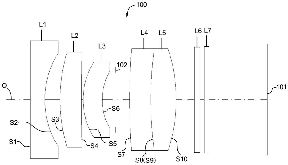
[0089] The structural diagram of the optical lens 100 disclosed in the first embodiment of the present application is figure 1 As shown, the optical lens 100 includes a first lens L1, a second lens L2, aperture 102, a third lens L3, a fourth lens L4, a fifth lens L5, and filtration, a third lens L3, a fourth lens L4, a third lens L5, and a fifth lens L5, a fifth lens L5, a fifth lens L5. Light L6 and protective glass L7. Among them, the material of the first lens L1, the second lens L2, the third lens L3, the fourth lens L4, and the fifth lens L5 can be referred to in the above specific embodiments, and will not be described later.

[0090] Further, the side surface S1 of the first lens L1, the web side surface S2 is respectively formed in the near optical axis O, and the side surface S3 of the second lens L2, and the image side surface S4 is convex and concave respectively. . The side surface S5 of the third lens L3, and the like side surface S6 is a convex surface and a concave ...

no. 2 example

[0099] Please refer to image 3 , image 3 A structural diagram of the optical lens 100 of the second embodiment of the present application. The optical lens 100 includes a first lens L1, a second lens L2, aperture 102, a third lens L3, a fourth lens L4, a third lens L5, a filter L6, a third lens L3, a fourth lens L4, a third lens L5, a filter L6, a third lens L3, a fourth lens L4, a third lens L5, a filter L6, a third lens L3, a fourth lens L4, a fifth lens L5 And protect the glass L7. Among them, the material of the first lens L1, the second lens L2, the third lens L3, the fourth lens L4, and the fifth lens L5 can be referred to in the above specific embodiments, and will not be described later.

[0100] Further, the first lens L1, the second lens L2, the third lens L3, the fourth lens L4, and the fifth lens L5 may be described with reference to the above embodiment, and details are not described herein again.

[0101]In the second embodiment, the focal length f = 5.74 mm of the o...

no. 3 example

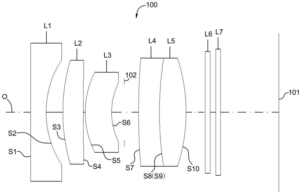
[0109] Please refer to Figure 5 , Figure 5 A structural diagram of the optical lens 100 of the third embodiment of the present application is shown. The optical lens 100 includes a first lens L1, a second lens L2, aperture 102, a third lens L3, a fourth lens L4, a third lens L5, a filter L6, a third lens L3, a fourth lens L4, a third lens L5, a filter L6, a third lens L3, a fourth lens L4, a third lens L5, a filter L6, a third lens L3, a fourth lens L4, a fifth lens L5 And protect the glass L7. Among them, the material of the first lens L1, the second lens L2, the third lens L3, the fourth lens L4, and the fifth lens L5 can be referred to in the above specific embodiments, and will not be described later.

[0110] Further, the first lens L1, the second lens L2, the third lens L3, the fourth lens L4, and the fifth lens L5 may be described with reference to the above embodiment, and details are not described herein again.

[0111] In the third embodiment, the focal length f = 5.7 mm...


PUM


Abstract

The invention discloses an optical lens, a camera module, electronic equipment and an automobile. The optical lens comprises a first lens, a second lens, a third lens, a fourth lens and a fifth lens which are sequentially arranged from an object side to an image side along an optical axis; the first lens has negative refractive power, the object side surface of the first lens is a plane, and the image side surface of the first lens is a concave surface; the second lens has positive refractive power, and the object side surface of the second lens is a convex surface; the third lens has refractive power, the object side surface of the third lens is a convex surface, and the image side surface of the third lens is a concave surface; the fourth lens has negative refractive power, the object side surface of the fourth lens is a convex surface, and the image side surface of the fourth lens is a concave surface; and the fifth lens element with positive refractive power has a convex object-side surface and a convex image-side surface. According to the optical lens, the camera module, the electronic equipment and the automobile provided by the invention, the resolution and the imaging definition of the optical lens can be improved while the light, thin and miniaturized design is met, and the high-definition imaging requirement of people on the optical lens is met.

Description

Technical field [0001] The present invention relates to the field of optical imaging, and more particularly to an optical lens, an imaging module, an electronic device, and a car. Background technique [0002] At present, with the development of the imaging technology, people's requirements for optical lenses are increasing, and the structural characteristics of light and miniaturization have gradually become the development trend of optical lenses. In the relevant technique, under the design trend of light thin miniaturization of optical lenses, the resolution of optical lenses is low, and the quality of imaging is not clear enough, which is difficult to meet the high-definition imaging requirements of optical lenses. Inventive content [0003] The embodiment of the present invention discloses an optical lens, an imaging module, an electronic device, and a vehicle that enhances the resolution and imaging clarity of the optical lens while achieving a light and miniaturized desig...

Claims


Application Information

Patent Timeline
IPC IPC(8): G02B13/00G02B13/18G03B30/00
CPCG02B13/0045G02B13/18
Inventor 蔡雄宇乐宇明赵迪
Owner TIANJIN OFILM OPTO ELECTRONICS CO LTD
Why Eureka
Try Eureka