Angle-adjustable network camera equipment and use method thereof

A network camera, adjustable technology, used in image communication, color TV parts, TV system parts and other directions, can solve the problem that the camera angle cannot be adjusted, and achieve the effect of stable rotation

Pending Publication Date: 2021-07-23
张海林
View PDF0 Cites 0 Cited by
  • Summary
  • Abstract
  • Description
  • Claims
  • Application Information

AI Technical Summary

Problems solved by technology

[0003] The object of the present invention is to provide an angle-adjustable network camera device to solve the problem that most of the network camera devices in the prior art are fixed and the camera angle cannot be adjusted in the above-mentioned background technology

Method used


Image

  • Angle-adjustable network camera equipment and use method thereof
  • Angle-adjustable network camera equipment and use method thereof
  • Angle-adjustable network camera equipment and use method thereof

Examples


Embodiment 1

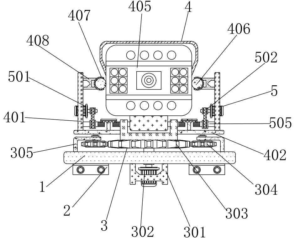
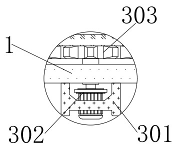
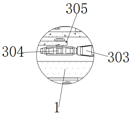
[0031] An angle-adjustable network camera device, comprising a first horizontal plate 1 and a first L-shaped plate 2, the first L-shaped plate 2 is fixedly connected to the left and right sides of the lower surface of the first horizontal plate 1, and the first L-shaped plate The plate 2 is screwed to the external building through two bolts, and a rotating device 3 is installed above the first horizontal plate 1, and the rotating device 3 includes a first H-shaped plate 301, a first motor 302, a first gear 303, and a second gear 304 , the second L-shaped plate 305 and the concave-shaped plate 306, the upper surface of the first H-shaped plate 301 is fixedly connected with the middle outer wall of the lower surface of the first horizontal plate 1, and the middle interior of the first H-shaped plate 301 is fixedly connected with the first Motor 302, the model of the first motor 302 is 3GB-555, the top of the first motor 302 is provided with the first gear 303, the first gear 303 ...

Embodiment 2

[0033] As an option, see figure 1 , 4, 5 and 6, angle-adjustable network camera equipment, camera device 4 is installed on the top of concave plate 306, camera device 4 comprises vertical plate 401, the second horizontal plate 402, the first gear bar 403, rectangular block 404, camera Body 405, ball 406, housing 407 and second H-shaped plate 408, left and right vertical plates 401 are located outside the concave plate 306, the lower surface of the first vertical plate 401 is fixed with the second horizontal plate 402, the left and right second The inner side of the horizontal plate 402 is fixedly connected with the outer wall of the concave plate 306, the top of the second horizontal plate 402 is provided with a first gear bar 403, the middle outer wall of the first gear bar 403 is connected with the inner rotation of the concave plate 306, the left and right second The inner side of a gear bar 403 is fixedly connected with a rectangular block 404, the first gear bar 403 can ...

Embodiment 3

[0036] As an option, see figure 1 , 5 And 6, the angle-adjustable network camera equipment, the inboard of riser 401 is equipped with adjusting device 5, and adjusting device 5 comprises second motor 501, first pulley 502, second pulley 503, belt 504, second gear bar 505, Gear plate 506 and vertical bar 507, the outer wall of left and right second motor 501 is fixedly connected with the inside of vertical plate 401, the model of second motor 501 is 68KTVY, the output shaft outer wall of second motor 501 is fixedly connected with first pulley 502, the second The output shaft of the second motor 501 can drive the first pulley 502 to rotate, the second pulley 503 is installed below the first pulley 502, the second pulley 503 is connected with the first pulley 502 through the belt 504, and the first pulley 502 is connected by the belt 504 Can drive the second pulley 503 to rotate, the inside of the second pulley 503 is fixedly connected with the second gear rod 505, the second pu...


PUM


Abstract

The invention discloses angle-adjustable network camera equipment, and the equipment comprises a first transverse plate and first L-shaped plates, wherein the left side and the right side of the lower surface of the first transverse plate are fixedly connected with the first L-shaped plates, and a rotating device is installed above the first transverse plate. According to the angle-adjustable network camera equipment, a first gear can be driven to rotate through an output shaft of a first motor, so that the first gear drives a rectangular block to rotate through a concave plate, and the rectangular block drives a camera body to rotate, so that the horizontal angle of the camera body is adjusted; a first belt wheel can be driven to rotate through an output shaft of a second motor, the first belt wheel drives a second belt wheel to rotate through a belt, the second belt wheel drives a fluted disc to rotate through a second gear rod, and the fluted disc drives a rectangular block to rotate through a first gear rod; therefore, the rectangular block drives the camera body to rotate in the vertical direction.

Description

technical field [0001] The invention relates to the technical field of digital video monitoring, in particular to an angle-adjustable network camera device. Background technique [0002] Digital Video Surveillance System The digital video surveillance system is a new security protection system based on the advanced image acquisition tool "camera", combined with sound monitors, alarm detectors, alarm detectors and some system control equipment Automation technology Automation technology, digital video monitoring system is characterized by its large amount of information, intuitive vision, easy storage and analysis of on-site information, complete system functions, flexible control, saving a lot of manpower and material resources for security guards and patrols, and strict and timely security precautions. Obtain more and more applications in the technical safety protection technology, and most of the network camera equipments in the prior art are fixed, the camera angle cannot...

Claims


Application Information

Patent Timeline
Patent Type & Authority Applications(China)
IPC IPC(8): H04N5/225H04N5/232H04N7/18
CPCH04N7/18H04N23/50H04N23/51H04N23/695
Inventor 张海林
Owner 张海林
Why Eureka
Try Eureka