Multi-part connector assembly

A technology of connector components and holding components, which is applied in the direction of pipeline connection arrangement, hose connection device, coupling, etc., can solve the problems of large installation space, etc., and achieve the effect of increasing pull-out friction and reliable connection

Pending Publication Date: 2021-07-23
OETIKER SCHWEIZ AG
View PDF8 Cites 0 Cited by
  • Summary
  • Abstract
  • Description
  • Claims
  • Application Information

AI Technical Summary

Problems solved by technology

Furthermore, conventional snap-fit ​​connectors require considerable installation space in the axial direction and have an overall diameter much larger than that of the hose

Method used


Image

  • Multi-part connector assembly
  • Multi-part connector assembly
  • Multi-part connector assembly

Examples


Embodiment Construction

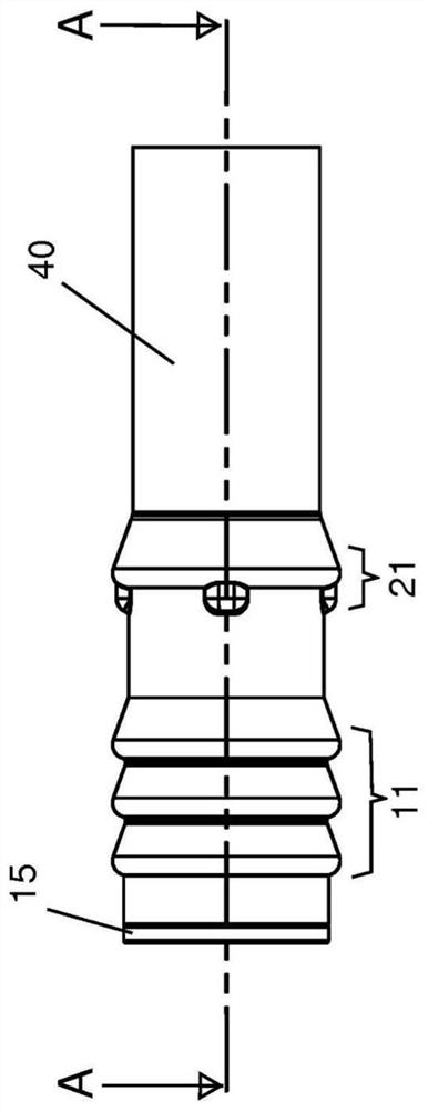
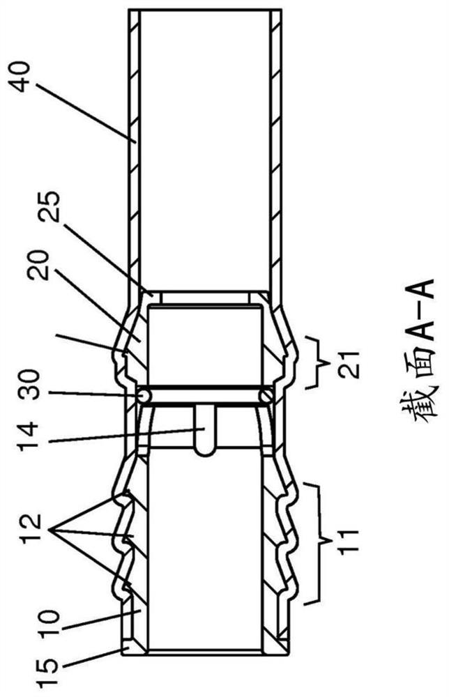
[0020] Figure 1a shows the to-be-connected Figure 2a Hose end 40 of sleeve 50 is shown. The hose end 40 fits snugly onto the outer surfaces of the first and second members 10 , 20 such that its outer profile is similar to that of the first and second members 10 , 20 . Only the flange portion 15 of the first member 10 remains outside the hose 40, and Figure 1a and 1d is shown on the far left. From Figure 1c and Figure 2c These details are best seen and understood in the cross-sectional view of .

[0021] Figure 1c A connector assembly consisting essentially of three parts is shown: a first retaining member 10 to engage the hose 40 and socket 50, a second retaining member 20 to engage the hose 40, and an O-ring 30 form A sealing element is inserted axially between the first and second members 10 , 20 and is adapted to form a seal between the outer surface of the sleeve 50 and the inner surface of the hose 40 .

[0022] The first retaining member 10 has a first flang...


PUM


Abstract

A multi-part connector assembly is provided which realises a compact snap coupling between a hose (40) and a pipe socket (50) with only a single potential leaking position and requiring only a minimum number of parts:a first retaining member (10), a second retaining member (20) and a sealing element (30) sandwiched therebetween in the axial direction of the connector assembly.

Description

technical field [0001] The invention relates to a connection device and method for connecting a hose to a socket or socket as a so-called quick connector or snap-in connector. Background technique [0002] Quick or snap-fit ​​connectors are widely used in a variety of applications, especially in automotive and industrial applications for joining fluid transfer conduits. A hose made of a flexible polymer material needs to be quickly connected to the socket and reliably sealed with the socket. The hose forms the female part of the fluid connection, the spigot forms the male part of the fluid connection, and the connector assembly shall enable a quick and fully airtight connection of the two parts with a snap fit. [0003] A conventional snap-fit ​​connector has a first retainer portion for receiving a male socket (hereinafter also referred to as a nipple or socket) and a second retainer portion for engaging a female hose. Both retainer parts need to be provided with sealing ...

Claims


Application Information

Patent Timeline
IPC IPC(8): F16L33/30F16L33/18F16L37/098F16L37/133F16L47/24
CPCF16L33/18F16L33/30F16L37/0985F16L37/133F16L47/24
Inventor M.莱曼
Owner OETIKER SCHWEIZ AG
Why Eureka
Try Eureka