Multi-phase LLC resonance DC/DC circuit

A resonant circuit and circuit technology, applied in the direction of electrical components, adjusting electrical variables, control/regulation systems, etc., can solve problems such as uneven current in multi-phase LLC resonant DC/DC circuits, achieve filtering and voltage stabilization effects, and improve Effect of polyphase current unbalance phenomenon

Pending Publication Date: 2021-07-27
SUNGROW POWER SUPPLY CO LTD
View PDF0 Cites 0 Cited by
  • Summary
  • Abstract
  • Description
  • Claims
  • Application Information

AI Technical Summary

Problems solved by technology

[0006] In view of this, the present invention provides a multi-phase LLC resonant DC/DC circuit to realize the improvement of serious inadequacy in the multi-phase L

Method used


Image

  • Multi-phase LLC resonance DC/DC circuit
  • Multi-phase LLC resonance DC/DC circuit
  • Multi-phase LLC resonance DC/DC circuit

Examples


Example

[0087] A simulation comparison example is given below:

[0088] First set the following:

[0089] The input voltage is 1000V, the switching frequency is 30kHz, the output voltage is 682V, and the output power is 110 kW;

[0090] Resonant cavity parameter error: each phase resonance capacitor CR, resonance inductance LR, excitation inductance LM with a predetermined standard parameter is ± 5%, each phase specific deviation is set to 5% or -5%. Standard excitation inductance LM = 68μH, standard resonant capacitor Cr = 4.182μF, standard resonant inductance LR = 6.8 μH, the inherent resonant frequency is close to 30 kHz. The load is a DC resistance.

[0091] Then simulate:

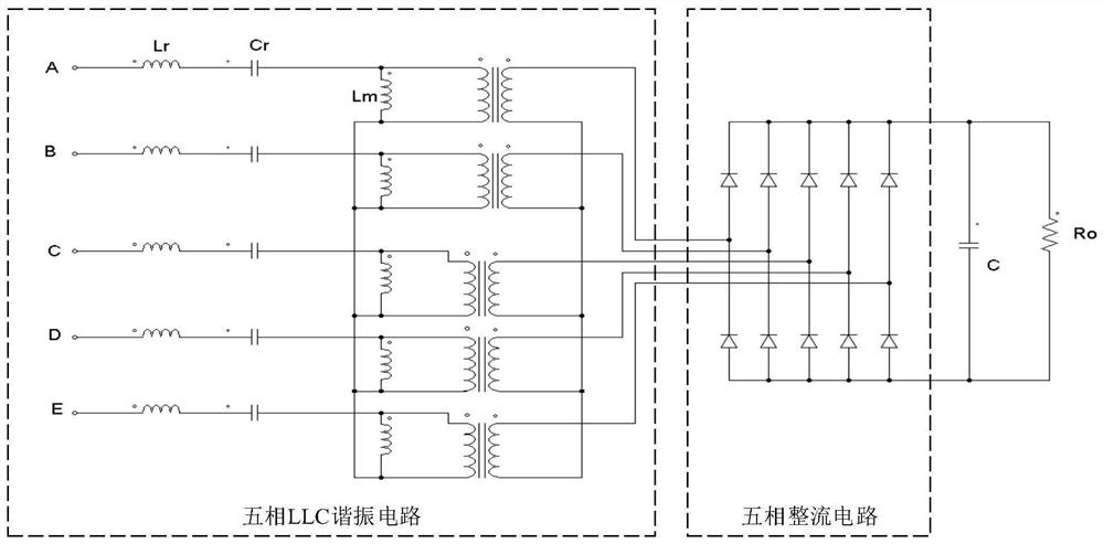
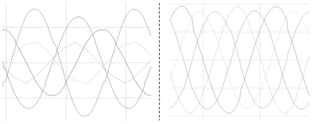
[0092] Such as figure 1 In the following scheme, the filter capacitor C uses a large capacitor 500μF. Simulation results show that the maximum current in the five-phase current is roughly a magnitude of the amplitude difference and the minimum current is very obvious, and the degree of unbalancedness of the five-ph...


PUM


Abstract

The invention discloses a multi-phase LLC resonance DC/DC circuit. The number of phases of the multi-phase LLC resonance DC/DC circuit is larger than or equal to 5, and the multi-phase current imbalance phenomenon is improved on the premise that the voltage stabilization and filtering effects are guaranteed. The multi-phase LLC resonance DC/DC circuit comprises a multi-phase LLC resonance circuit, a multi-phase rectification circuit and a CLC filter circuit which are connected in sequence, the CLC filter circuit comprises an input capacitor C1, an inductor L and an output capacitor C2, and C1 is smaller than C2.

Description

technical field [0001] The present invention relates to the technical field of power electronics, and more specifically, relates to a multi-phase LLC resonant DC / DC circuit. Background technique [0002] The three-phase LLC resonant DC / DC circuit includes: a three-phase LLC resonant circuit connected in sequence, a three-phase rectifier circuit and a filter capacitor. In order to improve the power density, it is considered to directly expand the three-phase LLC resonant DC / DC circuit to more phase LLC resonant DC / DC circuits, such as figure 1 The five-phase LLC resonant DC / DC circuit shown. [0003] In the multi-phase LLC resonant DC / DC circuit, the LLC resonant circuits of each phase work on the basis of transformers. The excitation inductance Lm in the LLC resonant circuit is the excitation inductance of the primary side of the transformer, and the resonant inductance Lr is the equivalent leakage reactance of the primary side of the transformer. The leakage inductance Lr...

Claims


Application Information

Patent Timeline
IPC IPC(8): H02M1/14H02M1/15H02M3/24
CPCH02M1/14H02M1/15H02M3/24
Inventor 王佳宁裴伟胡嘉汶庄加才
Owner SUNGROW POWER SUPPLY CO LTD
Why Eureka
Try Eureka