Two-dimensional body position adjusting device for radiology department
An adjustment device and a two-dimensional technology, applied in transmission devices, gear transmission devices, and instruments for radiological diagnosis, can solve problems such as unsatisfactory shooting effects, inability to meet the two-dimensional angle transformation of joint positions, and high misdiagnosis rate. The shooting effect is ideal, the body position is fixed in various ways, and the misdiagnosis rate is low.
- Summary
- Abstract
- Description
- Claims
- Application Information
AI Technical Summary
Problems solved by technology
Method used
Image
Examples
Embodiment 1
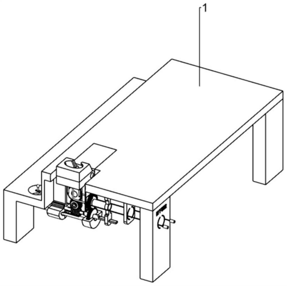
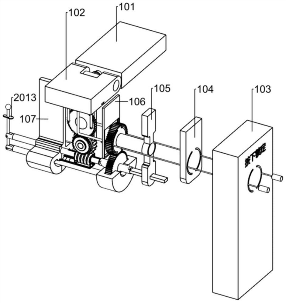
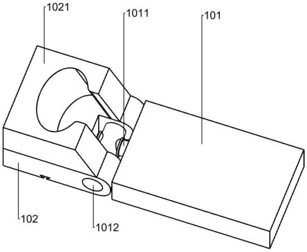
[0057] Such as Figure 1-16 shown
[0058]A radiology two-dimensional body position adjustment device according to the present invention includes a control part, an X-axis assembly and a Y-axis assembly. The control part, the X-axis assembly and the Y-axis assembly are all non-metallic products. The control part of the control part The rotating worm (203) of the X-axis assembly and the screw (303) of the Y-axis assembly are movably connected to the main shaft (202) at the same time, and the axial movement or rotation around the axis of the control main shaft (202) is controlled to respectively drive the The screw (303) and the rotating worm (203) work; the large gear (206) of the X-axis assembly is rotated by the rotating worm (204) of the X-axis assembly through the rotating worm (203), and the large gear (206) Both sides are provided with X-direction universal joints (208) through transmission rods (207). When the control main shaft (202) rotates around the axis, the X-dire...
Embodiment 2
[0061] like Figure 17-20 shown
[0062]The two-dimensional body position adjustment device of the radiology department has the following methods for connecting the auxiliary plate (101), the rotating plate (102), the X-axis assembly, and the Y-axis assembly according to different usage scenarios : the two-dimensional body position adjustment device of radiology department also includes shell frame (A1), auxiliary orifice plate (A101), connecting folding frame (A1062), transmission folding rod (A207), front end cover (41), rear end cover ( 42), backing plate (43), rectangular block (51), sliding rod (52), sliding block (521), rectangular frame (522), round end plate (523), fixed sliding frame (53), slide channel Hole (60), rotating sliding frame (61), round end cover (62) and stepped shaft (63), described shell frame (A1) and described bed body (1) shape are identical, but only keep described X axis assembly, the upper part of the Y-axis assembly, and a groove above the orig...
Embodiment 3
[0065] like Figure 21-31 shown
[0066] The sliding rod (52) and the rotating plate (102) are set as required: the auxiliary plate is replaced by an auxiliary groove plate (B101), and the fixedly connected X-axis column of the rotating plate (102) is replaced by a double hole Shaft column (B1010), two slider grooves (B1011) are opened on the surface of the auxiliary groove plate (B101), two column grooves (B1013) are opened in the middle of the auxiliary groove plate (B101), and the auxiliary groove plate (B101) Rack grooves (B1014) are respectively opened inside the column grooves (B1013), and the slider grooves (B1011) and the rack grooves (B1014) are connected through connecting grooves (B1012), so The auxiliary slot plate (B101) has a gear slot (B1015) in the middle between the two rack slots (B1014), a gear shaft (B1016) is arranged in the middle of the gear slot (B1015), and the rectangular frame ( 522) is provided with a rod sleeve (525) at the joint with the sliding...
PUM
 Abstract
Description
Claims
Application Information
 - R&D Engineer
- R&D Manager
- IP Professional
- Industry Leading Data Capabilities
- Powerful AI technology
- Patent DNA Extraction
Browse by: Latest US Patents, China's latest patents, Technical Efficacy Thesaurus, Application Domain, Technology Topic, Popular Technical Reports.
© 2024 PatSnap. All rights reserved.Legal|Privacy policy|Modern Slavery Act Transparency Statement|Sitemap|About US| Contact US: help@patsnap.com


