Angle detection device and electric power steering device using same

An electric power steering and angle detection technology, applied in electric steering mechanism, power steering mechanism, measuring device and other directions, can solve the problems of angle detection value motor rotation angle error and motor control performance deterioration, and achieve the effect of suppressing angle error

Active Publication Date: 2021-07-30
MITSUBISHI ELECTRIC CORP
View PDF9 Cites 0 Cited by
  • Summary
  • Abstract
  • Description
  • Claims
  • Application Information

AI Technical Summary

Problems solved by technology

The sine signal and cosine signal for the rotation angle of the motor are output in the above-mentioned angle detector, but in the case where an error (offset component or higher harmonic component) is contained in these sine signal and cosine signal, or when the sine signal If the amplitude value of the cosine signal is different from that of the cosine signal, the angle detection value obtained from the sine signal and the cosine signal has an error with respect to the actual rotation angle of the motor, which causes a problem that the control performance of the motor will be deteriorated.

Method used


Image

  • Angle detection device and electric power steering device using same
  • Angle detection device and electric power steering device using same
  • Angle detection device and electric power steering device using same

Examples


Embodiment approach 1

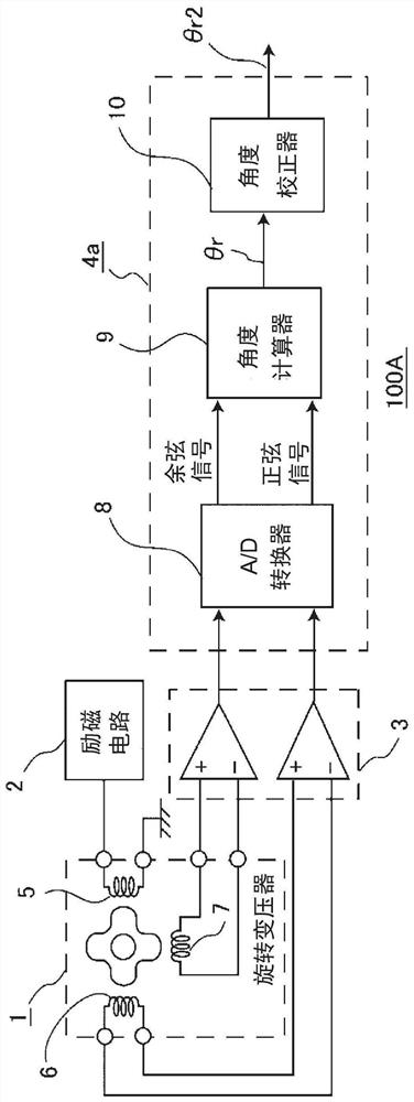
[0038] figure 1 It is a block diagram showing the configuration of the angle detection device according to the first embodiment. figure 1 Among them, the angle detection device 100A includes a resolver 1, an excitation circuit 2, a differential amplifier 3, and an angle calculation unit 4a. The resolver 1 includes an exciting coil 5 , a sine detection coil 6 for detecting the sine of the angle of a motor (not shown), and a cosine detection coil 7 for detecting the cosine of the angle of the motor.

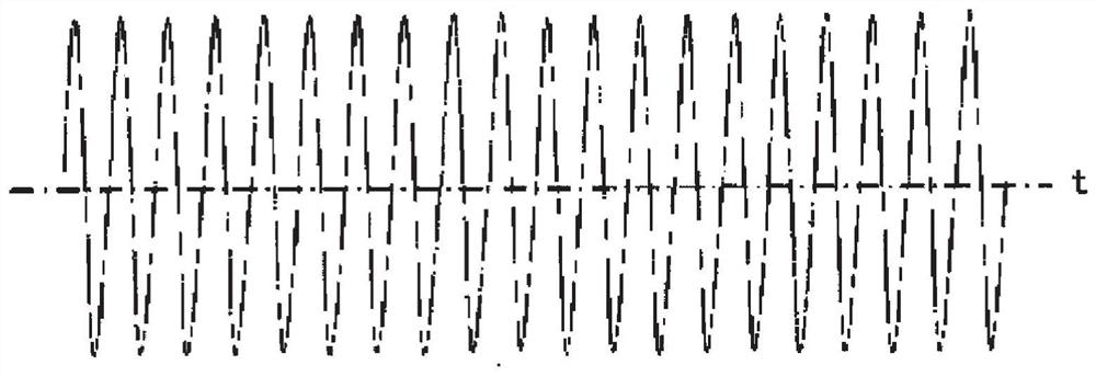
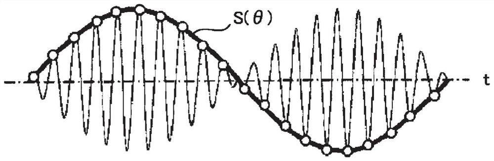
[0039] Resolver 1 via Figure 2A The AC signal shown is used to drive the excitation coil 5, so that the output terminal of the sinusoidal detection coil 6 is output by Figure 2B The sinusoidal signal S(θ) obtained by amplitude modulation of the sine of the angle of the motor shown. In addition, output to the output terminal of the cosine detection coil 7 by Figure 2C Cosine signal C(θ) obtained after amplitude modulation of the cosine of the motor angle shown. here, Figur...

Embodiment approach 2

[0089] Next, an angle detection device according to Embodiment 2 will be described.

[0090] The angle detection device according to the second embodiment differs from the first embodiment only in the offset correction value calculator, and the other parts are the same as those of the first embodiment. Therefore, here, the offset correction value calculator will be described.

[0091] Figure 10 It is a figure explaining the whole structure of the offset correction value calculator of the angle detection apparatus concerning Embodiment 2. The offset correction value calculator 201 according to Embodiment 2 includes a differentiator 106a, a low-pass filter 106b, a first integrator 106c, and a subtractor 106d. In addition, the offset correction value calculator 201 includes a cosine value calculator 201a, a sine value calculator 201b, a first multiplier 201c, a second multiplier 201d, a second integrator 201e, a third integrator 201f, and a fourth integrator 201g and the fift...

Embodiment approach 3

[0106] Next, an angle detection device according to Embodiment 3 will be described.

[0107] In the angle detection device according to Embodiment 3, only the offset correction value calculator described in Embodiment 2 is different, and other parts are the same as Embodiment 1 or Embodiment 2. Therefore, here, the offset correction value calculator will be described.

[0108] Figure 11 It is a figure explaining the whole structure of the offset correction value calculator of the angle detection apparatus concerning Embodiment 3. In the offset correction value calculator 301 according to the third embodiment, the third switch 301a and the third delayer 301b are provided in the subsequent stage of the fourth integrator 201g in the second embodiment, and the fifth integrator 201h The latter stage is provided with a fourth switch 301c and a fourth delayer 301d, when the second speed signal ω 0 When the fixed reference speed ω is equal to or higher, the first offset correction...


PUM


Abstract

The present invention achieves an angle detection device that suppresses angle error, even with respect to ordered components included in an angle signal other than the electrical angular frequency of the angle signal. The present invention calculates a second times-n angle signal (3thetar2) from a first sine wave signal (S(3thetar)) and a second sine wave signal (C(3thetar)) that are obtained from a first times-n angle signal (3thetar) that is obtained by multiplying an angle signal (thetar) by n (which is a real number that is not 1), calculates offset correction values (es, ec) for the first sine wave signal (S(3thetar)) and the second sine wave signal (C(3thetar)) from the second times-n angle signal (3thetar2), adds the offset correction value (es) calculated for the first sine wave signal (S(3thetar)) to the first times-n angle signal (3thetar) to correct the first sine wave signal (S(3thetar)), and adds the offset correction value (ec) calculated for the second sine wave signal (C(3thetar)) to the second sine wave signal (C(3thetar)) to correct the second times-n angle signal (3thetar2)).

Description

technical field [0001] This application relates to an angle detection device and an electric power steering device using the angle detection device. Background technique [0002] Generally, a resolver or an MR (Magneto Resistance: magnetoresistive) sensor is often used as an angle detector for detecting a rotation angle of a rotating machine, for example, a motor. The sine signal and cosine signal for the rotation angle of the motor are output in the above-mentioned angle detector, but in the case where an error (offset component or higher harmonic component) is contained in these sine signal and cosine signal, or when the sine signal If the amplitude value of the cosine signal is different from that of the cosine signal, the angle detection value obtained from the sine signal and the cosine signal has an error with respect to the actual rotation angle of the motor, thereby deteriorating the control performance of the motor. [0003] In this regard, Patent Document 1 disclo...

Claims


Application Information

Patent Timeline
Patent Type & Authority Applications(China)
IPC IPC(8): G01D5/244B62D5/04G01D5/20
CPCG01D5/204G01D5/2448B62D15/021B62D5/046B62D6/002G01D5/244
Inventor 森辰也古川晃
Owner MITSUBISHI ELECTRIC CORP
Why Eureka
Try Eureka