Variable valve gear for internal combustion engine

A technology for internal combustion engines and valves, applied to valve devices, mechanical equipment, engine components, etc., can solve problems such as difficult to improve stability, difficult to extend stability of shaft sleeves, etc., to avoid fatal damage, easy to operate, and maintain sex-enhancing effect

Inactive Publication Date: 2014-11-26
MITSUBISHI MOTORS CORP
View PDF7 Cites 0 Cited by
  • Summary
  • Abstract
  • Description
  • Claims
  • Application Information

AI Technical Summary

Problems solved by technology

However, since the first cam and the second cam are arranged in imitation of the arrangement of a pair of intake valves or a pair of exhaust valves assembled on the cylinder head, the dimension between the first cam and the second cam is restricted, making it difficult to Extend the hub until stability is ensured
Therefore, the bosses in Patent Documents 1 and 2 are restricted to have an overall length shorter than or equal to the width direction of the second cam, and it is difficult to improve stability.

Method used


Image

  • Variable valve gear for internal combustion engine
  • Variable valve gear for internal combustion engine
  • Variable valve gear for internal combustion engine

Examples


Embodiment Construction

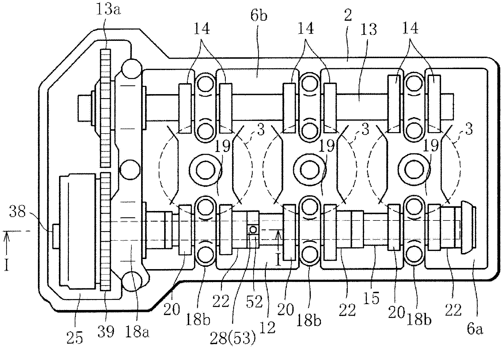
[0058] Below, according to Figure 1 to Figure 9 The present invention will be described with reference to one embodiment shown.

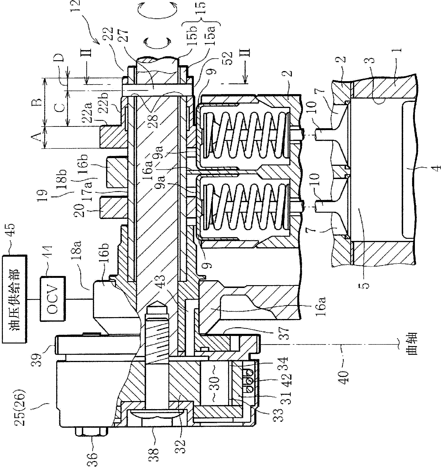
[0059] figure 1 A plane representing an internal combustion engine, such as a three-cylinder (multi-cylinder) reciprocating engine (hereinafter simply referred to as an engine), figure 2 means along figure 1 In the cross section of line II in the figure, 1 in the figure is the cylinder block of the engine, and 2 is the cylinder head mounted on the head of the cylinder block 1.

[0060] Among them, on the cylinder block 1, such as figure 1 and figure 2 It is shown that three cylinders 3 are formed along the front and rear direction of the engine (only partial cylinders are shown). Each of these cylinders 3 accommodates reciprocating pistons 4 (only figure 2 icon).

[0061] Combustion chambers 5 corresponding to the respective cylinders 3 are formed on the lower surface of the cylinder head 2 . A pair of intake ports 7 (two) for intake and...


PUM


Abstract

In a variable valve actuation device for an internal combustion engine, a hollow boss (22b) is fitted around the outer periphery of an outer camshaft (15a) and protrudes from one side of a second cam (22a) located opposite a first cam (20) in the width direction of the second cam over a distance greater than the width of the second cam, in order to suppress misalignment of the boss.

Description

technical field [0001] The present invention relates to a variable valve device for an internal combustion engine, wherein the phase of one cam of a pair of cams driving a pair of intake valves or a pair of exhaust valves is changed relative to that of the other cam by using a cam phase changing device. Background technique [0002] In a reciprocating engine (internal combustion engine) mounted on an automobile, a variable valve device is mounted on the cylinder head in order to cope with engine exhaust gas and improve pumping loss. [0003] The variable valve device has a structure in which the phase between valves of multiple valves (a pair of intake valves and a pair of exhaust valves) commonly used in an engine is variable, and the opening period of the multiple valves is changed. For example, there is a configuration in which, among a pair of cams that drive a pair of intake valves or a pair of exhaust valves, the phase of the other cam is changed with respect to one of...

Claims


Application Information

Patent Timeline
Patent Type & Authority Patents(China)
IPC IPC(8): F01L1/34
CPCF01L2001/34483F01L2103/02F01L1/143F01L2001/0476F01L2001/0473F01L1/053F01L1/3442F01L2303/02F01L1/34F01L13/00
Inventor 吉贺大辅松永礼俊
Owner MITSUBISHI MOTORS CORP
Why Eureka
Try Eureka