Rotation-angle-detecting apparatus
a detection apparatus and rotating angle technology, applied in the direction of galvano-magnetic devices, instruments, stray field compensation, etc., can solve the problems of reducing the angle error of signals, reducing the angle error, and unable to provide output signals with small angle errors and distortion, etc., to achieve the effect of suppressing the angle error
- Summary
- Abstract
- Description
- Claims
- Application Information
AI Technical Summary
Benefits of technology
Problems solved by technology
Method used
Image
Examples
example 1
[0095]FIG. 16 shows one example of magnetic sensors having bridge circuits X and Y comprising SVGMR devices. The depicted device arrangement corresponds to that of Sample 1-3 in Table 1 explained later. In the bridge circuit X, four rectangular SVGMR devices 201a-201d are formed on a substrate, the devices 201b and 201c being connected to a power supply terminal Vcc, the devices 201a and 201d being connected to a ground terminal GND, the devices 201a and 201b being connected to one output terminal Vx1, and the devices 201c and 201d being connected to the other output terminal Vx2. The longitudinal directions of the devices 201a-201d are inclined by angles θdip-R1 to θdip-R4 to an axis 202 parallel to the magnetization directions of pinned layers shown by the arrows. In the bridge circuit Y, four rectangular SVGMR devices 203a-203d formed on a substrate are perpendicular to the corresponding devices 201a-201d in the bridge circuit X. Each device comprises pinned layers having magneti...
example 2
[0111]To suppress the power consumption of a magnetic sensor by increasing the resistance of the SVGMR device, the device may have a longitudinal length of several tens of micrometers to about 100 μm. Such long device has large shape-induced anisotropy of a free layer in the SVGMR film, the AMR effect of the free layer is not negligible. Thus, in a magnetic sensor having the same device arrangement as in Example 1, θdip was changed as shown in Table 3, in which the angle of the device in a counterclockwise direction is expressed with “+,” and the value in parentheses was θdip-180°, when the AMR effect was taken into consideration and when it was not taken into consideration, to determine Δθerr by simulation. The results are shown in FIG. 25. In the formula (8), it was assumed from the thickness ratio of the free layer to the SVGMR film and the specific resistance of the NiFe film that the resistance contributing to AMR was 7500Ω, and dR′ was estimated as 22.5Ω assuming that the AMR ...
example 3
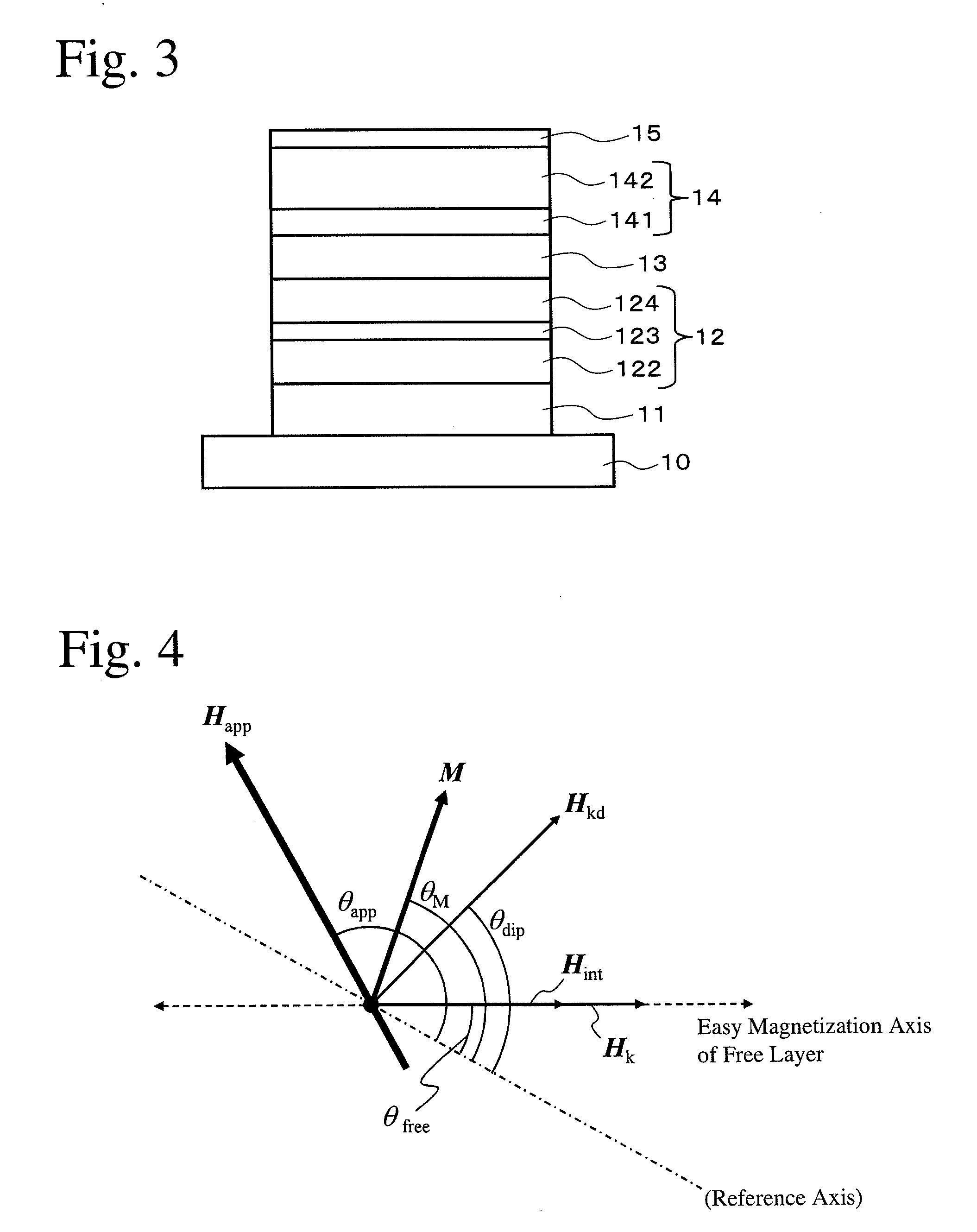
[0125]The most variable magnetic property of the SVGMR film is Hint (a magnetic field acting between the pinned layer and the free layer via the intermediate layer). Hint is variable depending on a so-called “orange peel effect” due to the thickness fluctuation and surface roughness of the intermediate layer, and temperatures such as an operation temperature, an ambient temperature, etc. To find the relation between Hint and Δθerr under the optimum device arrangement conditions (Sample 3-4), Δθerr was calculated by simulation at Hint-R1 of 0 kA / m, 0.08 kA / m, 0.16 kA / m, 0.40 kA / m and 0.80 kA / m, respectively, with the Hint(Hint-R5) of the device 213a was changed from −0.8 kA / m to +0.8 kA / m under the following conditions in the magnetic sensor shown in FIG. 26. The results are shown in FIG. 31.
[0126]Hint-R1 of device 211a=Hint-R4 of device 211d,
[0127]Hint-R2 of device 211b=Hint-R3 of device 211c,
[0128]Hint-R1=−Hint-R2,
[0129]Hint-R5 of device 213a=Hint-R8 of device 213d,
[0130]Hint-R6...
PUM
 Abstract
Description
Claims
Application Information
 - R&D
- Intellectual Property
- Life Sciences
- Materials
- Tech Scout
- Unparalleled Data Quality
- Higher Quality Content
- 60% Fewer Hallucinations
Browse by: Latest US Patents, China's latest patents, Technical Efficacy Thesaurus, Application Domain, Technology Topic, Popular Technical Reports.
© 2025 PatSnap. All rights reserved.Legal|Privacy policy|Modern Slavery Act Transparency Statement|Sitemap|About US| Contact US: help@patsnap.com


