Motor control device and electric power steering device provided with same

A motor control and motor technology, which is applied to electric steering mechanisms, power steering mechanisms, steering rods, etc., can solve problems such as torque generation efficiency drop, loss of step, estimated angle error, etc., to reduce angle error, simple structure, and suppress angle. effect of error

Active Publication Date: 2020-02-04
NSK LTD
View PDF9 Cites 1 Cited by
  • Summary
  • Abstract
  • Description
  • Claims
  • Application Information

AI Technical Summary

Problems solved by technology

[0005] That is, in the prior art of the above-mentioned Patent Document 1, when reaching the steering state and the environmental state in which the angle error due to the above-mentioned error factor occurs, an error occurs in the estimated angle calculated from the output shaft steering angle, and as a result, there is a possibility that Insufficient assistance due to loss of step and decrease in torque generation efficiency

Method used


Image

  • Motor control device and electric power steering device provided with same
  • Motor control device and electric power steering device provided with same
  • Motor control device and electric power steering device provided with same

Examples


no. 1 Embodiment approach

[0055] (structure)

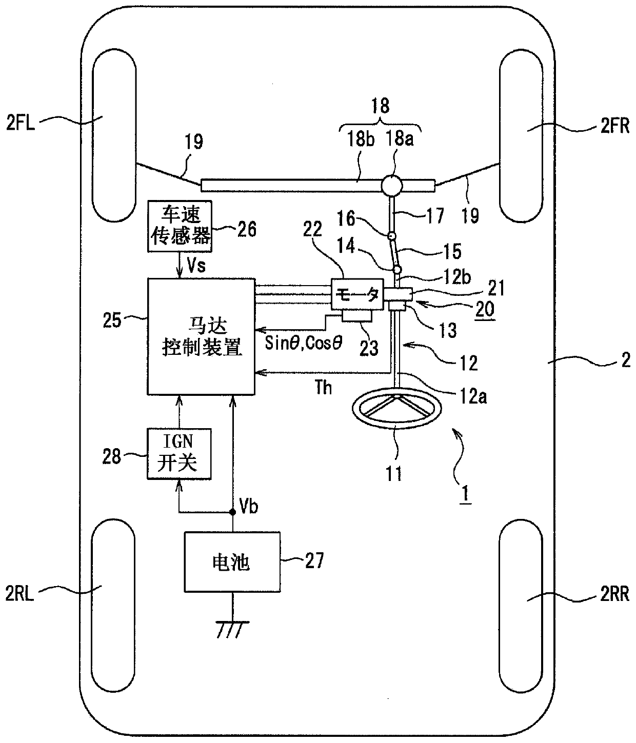
[0056] Such as figure 1 As shown, vehicle 2 according to the embodiment of the present invention has front wheels 2FR and 2FL and rear wheels 2RR and 2RL as left and right steering wheels. Front wheels 2FR and 2FL are steered by electric power steering device 1 .

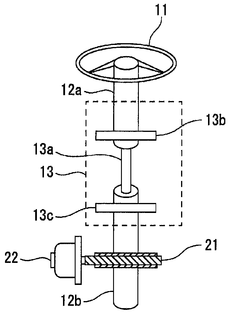
[0057] The electric power steering apparatus 1 has a steering wheel 11 , and a steering force applied to the steering wheel 11 by a driver is transmitted to a steering shaft 12 . The steering shaft 12 has an input shaft 12a and an output shaft 12b. One end of the input shaft 12 a is coupled to the steering wheel 11 , and the other end is coupled to one end of the output shaft 12 b via a steering torque sensor 13 .

[0058] Furthermore, the steering force transmitted to the output shaft 12 b is transmitted to the lower shaft 15 via the universal joint 14 , and is further transmitted to the pinion shaft 17 via the universal joint 16 . The steering force transmitted to the pinion shaft 17 is tr...

no. 2 Embodiment approach

[0326] Next, a second embodiment of the present invention will be described.

[0327] (structure)

[0328] In the first embodiment described above, the lead correction limit value SgL is calculated considering only the reduction gear error characteristic of the reduction gear 21. However, in the second embodiment, the output shaft rotation angle sensor 13c is also considered in addition to the reduction gear error characteristic. The detection error characteristic is different from the first embodiment described above. Other than that, it is the same structure as the said 1st Embodiment.

[0329] Hereinafter, the same reference numerals will be attached to the same structural parts as those of the first embodiment, and descriptions will be omitted as appropriate, and different parts will be described in detail.

[0330] (Inter-sensor error correction unit 54)

[0331] Such as Figure 23 As shown, the inter-sensor error correction unit 54 of the second embodiment has a conf...

no. 3 Embodiment approach

[0372] Next, a third embodiment of the present invention will be described.

[0373] (structure)

[0374] In the above-mentioned first embodiment, the leading gain is set to a value equal to or greater than "1" and the leading gain is multiplied by the output shaft angular velocity ωos to calculate the leading front and rear steering angular velocity ωosc. However, in the third embodiment, the leading gain is set to The value "0" or more is different from the first embodiment in that the lead correction update amount Cr is calculated by multiplying the lead gain by the output shaft angular velocity ωos. Also, it is different in that the leading-rear steering angular velocity ωosc is calculated by multiplying the output shaft angular velocity ωos by the leading correction update amount Cr. The structures other than these are the same as those of the above-mentioned first embodiment.

[0375] Hereinafter, the same reference numerals will be attached to the same structural part...


PUM


Abstract

Provided are a motor control device and an electrical power steering device which are configured to perform a correction for advancing an estimated motor electrical angle in response to a steering torque, and are thus capable of correcting an estimated angle error, acting in a delaying direction with respect to the steering direction, with a simple configuration. This motor control device (25) isprovided with a backup electrical angle detection circuit (24B), wherein: an inter-sensor error correction unit (54) calculates at least one advance gain (Gad) with respect to an input of a steering torque (Th) of at least predetermined torque value (Tht), and multiplies the advance gain (Gad) to an output shaft angular velocity ([omega] os) to calculate a post-advance steering angular velocity ([omega]osc) for correcting an estimated angle error in a delaying direction with respect to the steering direction. In addition, an estimated angle calculation unit (55) of the backup electrical angledetection circuit (24B) integrates the post-advance steering angular velocity ([omega]osc) and calculates a second motor rotation angle ([theta]m2), which is an estimated value of a motor rotation angle (theta), on the basis of the integrated value.

Description

technical field [0001] The present invention relates to a motor control device for driving and controlling an electric motor mounted on an electric power steering device. Background technique [0002] Conventionally, there have been technologies disclosed in Patent Documents 1 and 2 as a backup technique when a motor position sensor that detects a motor electrical angle of an electric motor mounted on an electric power steering apparatus fails. [0003] In the technique of Patent Document 1, a steering angle sensor is mounted on the side of the column output shaft in an electric power steering system, and the estimated angle calculated from the back electromotive force information of the electric motor that generates steering assist force and the detection information of the steering angle sensor are calculated. The resulting estimated angle is switched and used according to the steering speed. [0004] Here, the electric power steering device is generally configured such t...

Claims


Application Information

Patent Timeline
Patent Type & Authority Applications(China)
IPC IPC(8): H02P6/15B62D5/04B62D6/00H02P6/16B62D101/00B62D119/00B62D137/00
CPCB62D6/00H02P6/15B62D5/04H02P6/16H02P6/08H02P25/022H02P21/09H02P21/22B62D5/0409B62D5/0463B62D5/0484
Inventor 今村洋介
Owner NSK LTD
Why Eureka
Try Eureka