Cooling channel for winding overhang of stator, and stator comprising cooling channel of this type

A technology for cooling channels and winding ends, applied in the field of stators, can solve the problems of increasing the cost of cooling caps and design difficulties, and achieve the effect of improving sealing

Pending Publication Date: 2021-07-30
JHEECO E DRIVE AG
View PDF3 Cites 0 Cited by
  • Summary
  • Abstract
  • Description
  • Claims
  • Application Information

AI Technical Summary

Problems solved by technology

Of course, an additional component is not desirable as it increases the cost and design difficulty of the cooling cap

Method used


Image

  • Cooling channel for winding overhang of stator, and stator comprising cooling channel of this type
  • Cooling channel for winding overhang of stator, and stator comprising cooling channel of this type
  • Cooling channel for winding overhang of stator, and stator comprising cooling channel of this type

Examples


Embodiment Construction

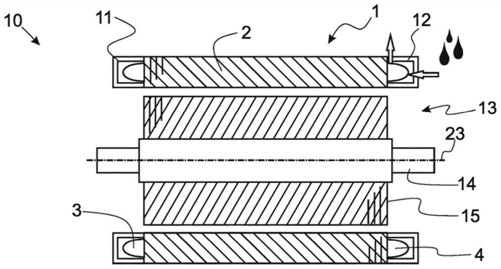
[0043] figure 1 A cross-sectional view of an electric machine 10 is shown, comprising a stator 1 and a rotor 13 arranged inside the stator. The stator 1 , in particular the laminated stator core 2 , is hollow cylindrical and has annular cooling channels 11 and 12 at both ends. The cooling channels 11 , 12 communicate with a fluid reservoir (not shown) for cooling by means of a fluid the winding ends 3; 4 formed or arranged in the cooling channels (see arrows, one in and one out). The rotor 13 is formed by a rotor shaft 14 and a rotor laminated core 15 , wherein the rotor can have, for example, permanent magnets, short-circuit rings or field windings, depending on the implementation. The electric machine 10 (and thus the stator 1 and the rotor 13 ) are designed rotationally symmetrically about an axis of rotation 23 .

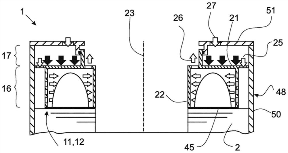
[0044] figure 2 A greatly simplified cross-sectional view is shown through a cooling channel 11 or 12 according to a preferred embodiment, which is arrange...


PUM


Abstract

The invention relates to a cooling channel for a winding overhang of an electrical machine, wherein, in order to conduct a cooling fluid, said cooling channel is designed with at least one inflow 25 and at least one outflow 26 and is annular for provision around the winding overhang 3, 4. In order to achieve improved sealing properties, the cooling channel has an axially movable contact pressure part 21 that is situated such that a cooling fluid flows against the contact pressure part 21, thus generating a contact pressure on the cooling channel.

Description

technical field [0001] The present disclosure relates to a cooling channel for the winding ends of an electrical machine and a stator comprising such a cooling channel. Background technique [0002] The term "electrical machine" is primarily understood to mean an electric motor or generator comprising a stator and a rotor, wherein the rotor is mounted rotatably relative to the stator about a common longitudinal axis. [0003] The stator includes, for example, a stator laminated core and current carrying windings. The windings can be arranged in grooves of the stator laminated core, which grooves are distributed over the circumference and are elongated in the axial direction. The winding forms a plurality of coils / half-coils, wherein the coils / half-coils consist of two elongated conductive sections in different grooves and two / one connection connecting these conductive sections at the end faces of the stator laminated core part. Only the portion of the winding that is axia...

Claims


Application Information

Patent Timeline
Patent Type & Authority Applications(China)
IPC IPC(8): H02K9/00H02K9/19H02K3/24H02K5/20H02K3/50
CPCH02K3/24H02K2209/00H02K3/505H02K9/16H02K9/00H02K3/50H02K5/203H02K9/197
Inventor 安德烈亚斯·伊万施滕申科马丁·诗道克
Owner JHEECO E DRIVE AG
Why Eureka
Try Eureka