Pedal type door handle and door

A door handle and foot-operated technology, which is applied to foot-operated door handles, and the door field including foot-operated door handles, can solve problems such as health and safety hazards.

Pending Publication Date: 2021-08-06
周丽媛
View PDF0 Cites 2 Cited by
  • Summary
  • Abstract
  • Description
  • Claims
  • Application Information

AI Technical Summary

Problems solved by technology

Therefore, the switch locking mode of existing contact type door handle and door has potential health and safety hazards

Method used


Image

  • Pedal type door handle and door
  • Pedal type door handle and door
  • Pedal type door handle and door

Examples


Embodiment 1

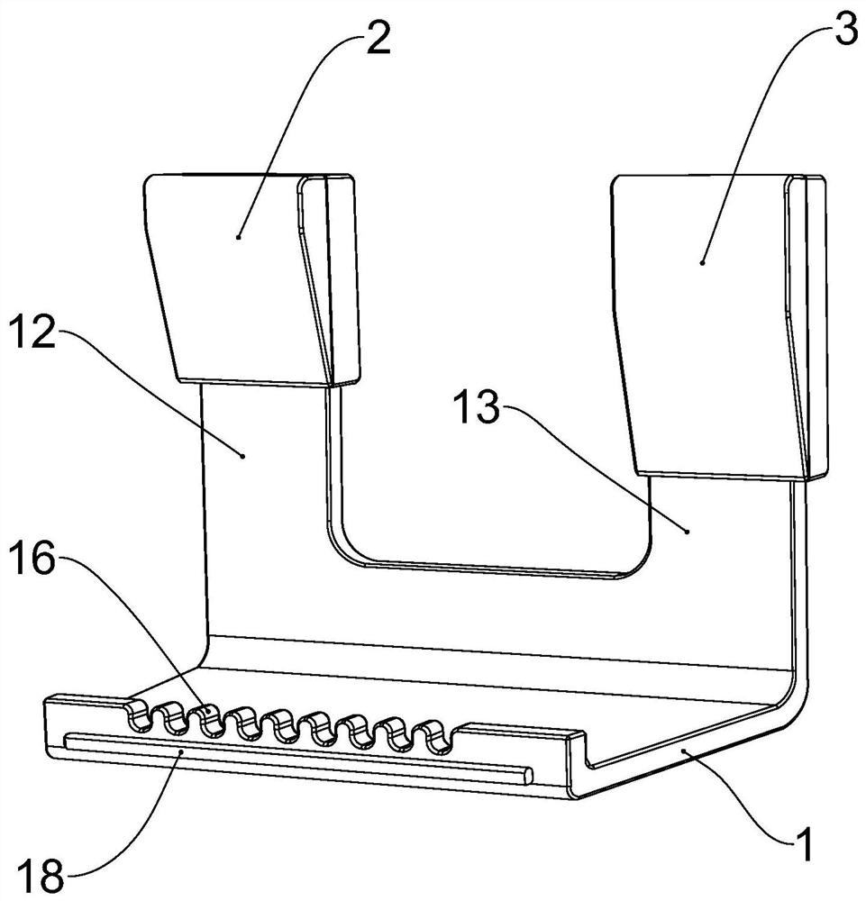
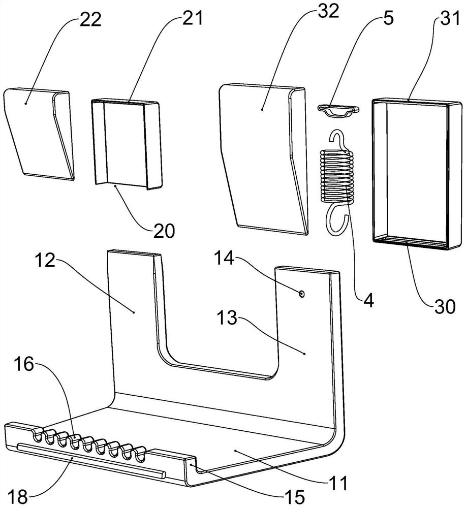
[0042] Such as Figure 1 to Figure 6 As shown, the door of this embodiment includes a movable door body 100, a fixed door frame 200, and a foot-operated door handle. The foot-operated door handle of this embodiment does not require traditional door handles and locks, and does not require direct contact with hands. To switch and lock, the switch and lock operation can be performed only by stepping on the foot; specifically, the foot-operated door handle includes a pedal 1, a pedal locking device 2, a pedal connecting device 3. The pedal connecting device 3 is fixedly connected to the movable door body 100, the pedal locking device 2 is fixedly connected to the fixed door frame 200, the pedal connecting device 3, the The foot pedal locking device 2 is respectively located at the bottom of the movable door body 100 and the inner lower part of the fixed door frame 200, and the foot pedal is provided between the bottom of the movable door body 100 and the ground. 1 An activity spa...

Embodiment 2

[0048] Such as Figure 7 , Figure 8 As shown, the difference between the door and the foot-operated door handle of this embodiment and the first embodiment is that the height of the locking vertical plate 12 is smaller than the height of the sliding vertical plate 13, and the locking hole 20 and The heights of the sliding grooves 30 are the same, which can also ensure that when the sliding vertical plate 13 is pedaled and slid to the bottom stop and the top is still in the sliding groove 30, the locking vertical plate 12 can be opened from the locking hole. 20 inner separation and downward prolapse.

[0049] The remaining features of this embodiment are the same as those of Embodiment 1.

Embodiment 3

[0051] Such as Figure 9 , Figure 10 As shown, the difference between the door and the foot-operated door handle of this embodiment and the first embodiment is that in this embodiment, the bottom plate 11 traverses through the movable space 101 below the movable door body 100 , The two outer ends of the bottom plate 11 are located on the inner and outer sides of the movable door body 100, and the part of the bottom plate 11 on the outer side of the movable door body 100 close to the fixed door frame 200 is reserved to avoid the fixed door frame 200. space, the locking vertical plate 12 and the sliding vertical plate 13 are connected to the middle of the bottom plate 11, and the bottom plate 11 can be stepped on both inside and outside of the movable door body 100, adopting this implementation For example, the scope of use is expanded, and the operation of opening and closing the door and locking the door can be realized on both sides of the inside and outside of the movable ...


PUM


Abstract

The invention discloses a pedal type door handle and a door comprising the pedal type door handle. The pedal type door handle comprises a pedal plate, a pedal plate locking device and a pedal plate connecting device. The pedal plate connecting device is fixedly connected with a movable door body, the pedal plate locking device is fixedly connected with a fixed door frame, the bottom of the pedal plate locking device is provided with a locking hole, and the bottom of the pedal plate connecting device is provided with a sliding groove. The pedal plate comprises a bottom plate, a locking vertical plate and a sliding vertical plate, an extension spring is arranged in the pedal plate connecting device and is fixedly connected with the pedal plate connecting device and the sliding vertical plate, and the sliding vertical plate penetrates through the sliding groove and then extends into the pedal plate connecting device. The locking vertical plate is separated from the pedal plate locking device when the pedal plate is stepped on, the sliding vertical plate slides upwards to reset when the pedal plate is loosened, the locking vertical plate can block the side face of the pedal plate locking device when the door is opened, the locking vertical plate penetrates through the locking hole and extends into the pedal plate locking device when the door is closed, and the movable door body and the fixed door frame are locked and fixed. The pedal type door handle can be widely applied to the field of doors.

Description

technical field [0001] The invention relates to a door accessory, in particular to a foot-operated door handle; in addition, the invention also relates to a door including the foot-operated door handle. Background technique [0002] In the prior art, for the doors of general public places, it is necessary to touch the handle of the sliding door with hands to switch and lock the door. For example, it is unrealistic to use induction or automatic doors for places such as relatively airtight public toilets, because the costs of purchase, installation, and maintenance are too high. With the improvement of living standards, people have higher and higher requirements for hygiene in public places, especially for users who love hygiene or even cleanliness. Ordinary public toilet door handles will cause great trouble to users, especially if they are touched by hand. The door handle still touches the body after closing the door, which affects the health and safety of users. The publi...

Claims


Application Information

Patent Timeline
IPC IPC(8): E05B53/00
CPCE05B53/001
Inventor 周丽媛易诗婷张学敏张瑶
Owner 周丽媛
Why Eureka
Try Eureka