
Hard rock tunnel boring machine

A tunnel boring machine and hard rock technology, applied in tunnels, mining equipment, earthwork drilling and mining, etc., can solve the problems of low construction efficiency and achieve the effect of improving efficiency

Inactive Publication Date: 2021-08-06
CHINA RAILWAY ENGINEERING EQUIPMENT GROUP CO LTD
View PDF2 Cites 0 Cited by
  • Summary
  • Abstract
  • Description
  • Claims
  • Application Information

AI Technical Summary

Problems solved by technology

[0005] The purpose of the present invention is to provide a hard rock tunnel boring machine, which is used to solve the technical problem of low construction efficiency caused by disassembling and assembling the screw conveyor when switching the conveying mode of the current hard rock tunnel boring machine

Method used


Image

  • Hard rock tunnel boring machine
  • Hard rock tunnel boring machine
  • Hard rock tunnel boring machine

Examples


specific Embodiment 1

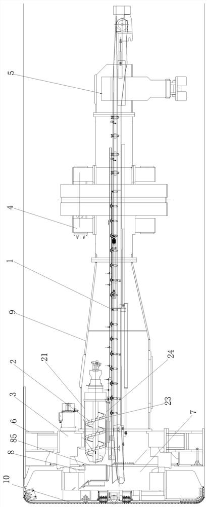
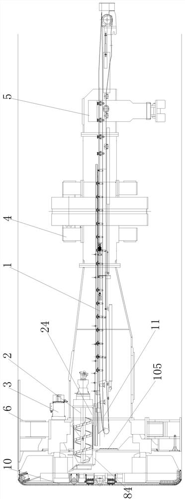
[0040] like figure 1As shown, the hard rock tunnel boring machine includes a main beam 9 and a cutter head 10, the main beam 9 is provided with a main drive 3, a steel arch installer, a bolter, a support propulsion system 4 and a rear support 5, and the main drive 3 is installed On the main beam 9, it is used to drive the cutter head 10 to rotate. The radially outer side of the main drive 3 is provided with a shield 6 for protecting the main drive 3, stabilizing the main drive 3 and reducing vibration during excavation. The back support 5 is welded and fixed with the main beam 9 . The main beam 9 and the above-mentioned components on the main beam 9 are all prior art, and will not be described in detail here.

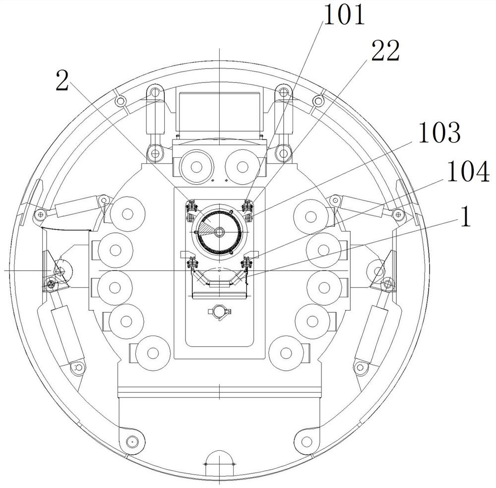
[0041] like Figure 1 to Figure 5 As shown, the rear side of the cutter head 10 of the hard rock tunnel boring machine is provided with a muck bin 7, the rear partition 71 of the muck bin 7 is fixed with the main drive fixing seat 31 of the main drive 3, and the dreg...

specific Embodiment 5

[0057] The difference between Embodiment 5 of the hard rock tunnel boring machine of the present invention and the above-mentioned Embodiment 1 is that in this embodiment, the slag discharge belt conveyor does not retreat in the spiral conveying slag discharge mode, and remains at the original position. .

specific Embodiment 6

[0058] The specific embodiment 6 of the hard rock tunnel boring machine of the present invention is different from the above-mentioned embodiment 1 in that: the bottom of the screw conveyor is provided with slide rails, and the track of the screw conveyor is located on the lower side of the screw conveyor, and the screw conveyor is supported to move forward and backward. .

[0059] Embodiment 7 of the hard rock tunnel boring machine of the present invention differs from the above embodiment 1 in that: a screw nut mechanism and a drive motor are used to drive the screw conveyor to move back and forth. In other embodiments, the position of the screw conveyor can also be manually adjusted.


PUM


Abstract

The invention relates to a hard rock tunnel boring machine. The hard rock tunnel boring machine comprises a main beam, a cutter head, a main drive, a slag collecting hopper, a slag discharging belt conveyor and a spiral conveyor; the hard rock tunnel boring machine comprises a spiral conveyor rail; the spiral conveyor rail and the main beam are relatively fixed; the spiral conveyor is movably arranged on the spiral conveyor rail; and the spiral conveyor is located at a slag discharging position in a spiral conveying slag discharging mode, and the spiral conveyor is located at a shutdown position in a belt conveying slag discharging mode. The spiral conveyor of the hard rock tunnel boring machine is movably arranged on the spiral conveyor rail; during use, the position of the spiral conveyor rail can be switched according to different working modes of the boring machine; and compared with a mode of dismantling the spiral conveyor, the boring machine has the advantages that the spiral conveyor does not need to be dismantled, the working mode switching efficiency is improved, and the technical problem that the construction efficiency is low due to the fact that the spiral conveyor needs to be disassembled and assembled when the conveying modes of an existing hard rock tunnel boring machine are switched is solved.

Description

technical field [0001] The invention relates to a hard rock tunnel boring machine. Background technique [0002] Hard rock tunnel boring machine (TBM for short) is a special construction machine for tunnel excavation. It has the functions of excavating and cutting soil, transporting sludge, tunnel support, etc., and is widely used in tunnel engineering. Open hard rock tunnel boring machines usually use belt conveyors for slag removal, which is more efficient in excavating strata with undetermined surrounding rocks. However, when excavating in weak and broken strata, problems such as mud inrush and water gushing are prone to occur due to unstable surrounding rocks. In this case, the amount of slag discharge cannot be controlled by the belt conveyor, resulting in the belt conveyor being easily crushed to death, and debris flow-like insertions are likely to flow into the cutter head, and even into the tunnel through the main beam manhole, resulting in excessive slag discharge f...

Claims


Application Information

Patent Timeline
Patent Type & Authority Applications(China)
IPC IPC(8): E21D9/087E21D9/12
CPCE21D9/087E21D9/12E21D9/124
Inventor 尹威华张文艳贺飞宁向可张啸杨耀宗张喜冬席杰
Owner CHINA RAILWAY ENGINEERING EQUIPMENT GROUP CO LTD
Learn More