Plastic concrete diaphragm wall seepage failure gradient quality detection test device
A technology of plastic concrete and test device, applied in measurement device, permeability/surface area analysis, suspension and porous material analysis, etc. Accurate test structure and the effect of reducing labor
- Summary
- Abstract
- Description
- Claims
- Application Information
AI Technical Summary
Problems solved by technology
Method used
Image
Examples
Embodiment 1
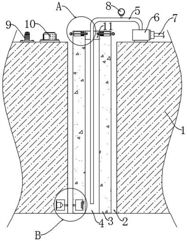
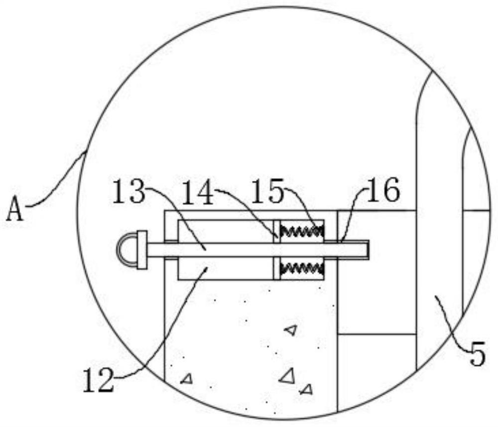
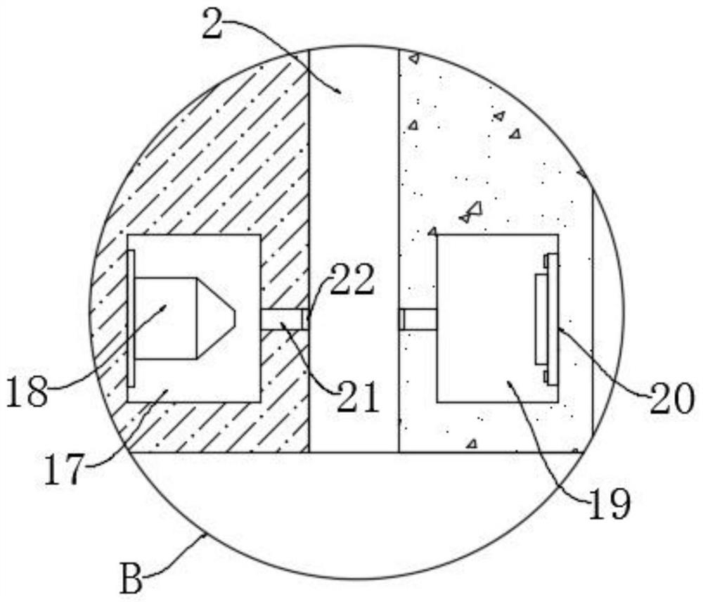
[0021] refer to Figure 1-3 , a plastic concrete anti-seepage wall penetration failure gradient quality testing device, including a base 1, the upper end of the base 1 is provided with a placement groove 2, the placement groove 2 is used to place a wall 3, and the water leaked from the wall 3 will be stored At the inner bottom of the placement tank 2, a wall 3 is arranged in the placement tank 2, and a test tank 4 is provided on the upper end of the wall body 3, and the test tank 4 is used for pressurizing the wall body 3, and a water pump 6 is provided on the upper end of the base body 1, The water inlet end of the water pump 6 is connected with a liquid inlet pipe 7, and the water outlet end of the water pump 6 is connected with a transmission pipe 5, and a pressure gauge 8 is installed on the transmission pipe 5, and the pressure gauge 8 is used to observe the pressure of the liquid injected into the test tank 4, and the test An airtight plug 11 is installed at the notch of...
Embodiment 2
[0030] refer to Figure 4-5 The difference between this embodiment and Embodiment 1 is that the lower end of the airtight plug 11 is provided with a vertical groove 28, and the vertical groove 28 is provided with a sliding block 25, the sliding block 25 is slidably connected with the vertical groove 28, and the upper end of the sliding block 25 It is elastically connected with the inner top of the vertical groove 28 by a telescopic spring 26. The outer side of the sealing plug 11 is provided with an annular groove 23. The annular groove 23 is located below the two limiting grooves 16. An annular air bag 24 is arranged in the annular groove 23. The annular air bag 24 can expand outwards after being inflated, and the annular airbag 24 and the vertical groove 28 are positioned at the upper space of the sliding block 25 and lead through the connecting pipe 27 .
[0031] In this embodiment, as the pressure of the liquid in the test tank 4 increases continuously, the pressure on the...
PUM
 Abstract
Description
Claims
Application Information
 - R&D
- Intellectual Property
- Life Sciences
- Materials
- Tech Scout
- Unparalleled Data Quality
- Higher Quality Content
- 60% Fewer Hallucinations
Browse by: Latest US Patents, China's latest patents, Technical Efficacy Thesaurus, Application Domain, Technology Topic, Popular Technical Reports.
© 2025 PatSnap. All rights reserved.Legal|Privacy policy|Modern Slavery Act Transparency Statement|Sitemap|About US| Contact US: help@patsnap.com


