Bee feeding box facilitating observation of bee state and use method thereof
A technology for breeding boxes and bees, which is applied to the field of bee breeding boxes where it is convenient to observe the state of bees, can solve the problems of inability to observe the situation of the breeding box from multiple angles, unable to adjust the height of the breeding box, and unfavorable for observing the state of bees, and achieves easy disassembly, Ease of cleaning and improved usability
- Summary
- Abstract
- Description
- Claims
- Application Information
AI Technical Summary
Problems solved by technology
Method used
Image
Examples
Embodiment 1
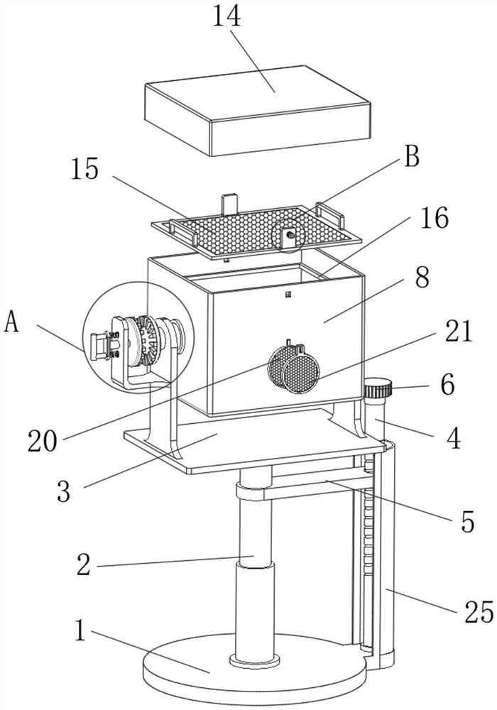
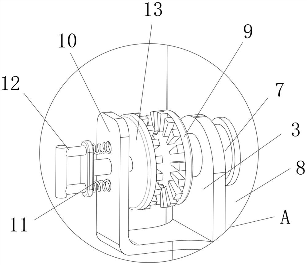
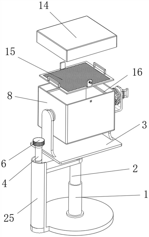
[0029] Example 1, please refer to figure 1 and image 3 , the present invention provides a kind of technical scheme: a kind of bee breeding box that is convenient to observe the state of bees, comprises base 1, the inside of base 1 is slid with lifting rod 2, the top of lifting rod 2 is fixedly provided with frame 3, and a A threaded rod 4 is rotated on the side, and a turning handle 6 is fixedly installed on the top of the threaded rod 4. The circumference of the turning handle 6 is concave. By setting the turning handle 6, it is convenient for researchers to rotate the threaded rod 4, and the researchers can rotate The phenomenon of slippage is not easy to occur, the surface of the threaded rod 4 is rotated with a connecting block 5, and the connecting block 5 is fixedly connected with the lifting rod 2, and the surface of the base 1 is located on one side of the threaded rod 4 with a fixed baffle 25. By setting the baffle 25, plays the role of protecting the threaded rod 4...
Embodiment 2
[0031] Example 2, please refer to figure 1 , image 3 and Figure 4 , the interior of the acrylic box 8 is provided with a separation device, the separation device includes a separation net 15, and the separation net 15 is slidably connected to the interior of the acrylic box 8, and the inner wall of the acrylic box 8 is located below the separation net 15. The limit block 16 is fixedly installed, and by setting The limiting block 16 plays the role of preventing the separation net 15 from continuing to move in the acrylic box 8 .
[0032] see figure 1 , image 3 and Figure 4 , a fixing block 17 is fixed on one side of the dividing net 15, a spring 18 is installed on the surface of the fixing block 17, and one end of the spring 18 is fixedly connected with a clamping block 19, and the clamping blocks 19 are symmetrically distributed on both sides of the dividing net 15. Both sides of the 19 are arc-shaped. By setting the arc-shaped clamping blocks 19, it is convenient for...
Embodiment 3
[0033] Example three, please refer to Figure 5-6 The surface of the acrylic box 8 is provided with a dustproof device at the position of the ventilation net 20, and the dustproof device includes a dustproof net 21. The dustproof net 21 is slidably connected to the surface of the acrylic box 8, and the top surface of the dustproof net 21 is provided with Through slot 22, the surface of the acrylic box 8 is located above the ventilating net 20, and there is a damping shaft 23 that rotates. One end of the damping shaft 23 is fixedly connected with a turning block 24. By setting the damping shaft 23, the space between the turning block 24 and the acrylic box 8 is increased. The friction force plays the role of the limiting block 24 .
[0034] see Figure 5-6, the top surface of the dustproof net 21 is convex, and the surface of the acrylic box 8 is located at the position of the turning block 24 with a gap, and by opening a gap on the surface of the acrylic box 8, so that the ra...
PUM
 Abstract
Description
Claims
Application Information
 - R&D
- Intellectual Property
- Life Sciences
- Materials
- Tech Scout
- Unparalleled Data Quality
- Higher Quality Content
- 60% Fewer Hallucinations
Browse by: Latest US Patents, China's latest patents, Technical Efficacy Thesaurus, Application Domain, Technology Topic, Popular Technical Reports.
© 2025 PatSnap. All rights reserved.Legal|Privacy policy|Modern Slavery Act Transparency Statement|Sitemap|About US| Contact US: help@patsnap.com


