Clock legalization method based on heterogeneous FPGA layout

A clock and heterogeneous technology, applied in the field of VLSI physical design automation, can solve the problems of design complexity and scale increase, and achieve the effect of avoiding wiring failure

Active Publication Date: 2021-08-06
FUZHOU UNIV
View PDF5 Cites 0 Cited by
  • Summary
  • Abstract
  • Description
  • Claims
  • Application Information

AI Technical Summary

Problems solved by technology

Relatively, its design complexity and scale are also increasing, which brings great challenges to heterogeneous FPGA layout

Method used


Image

  • Clock legalization method based on heterogeneous FPGA layout
  • Clock legalization method based on heterogeneous FPGA layout
  • Clock legalization method based on heterogeneous FPGA layout

Examples


Embodiment Construction

[0025] The present invention will be further described in detail below in conjunction with the accompanying drawings and specific embodiments.

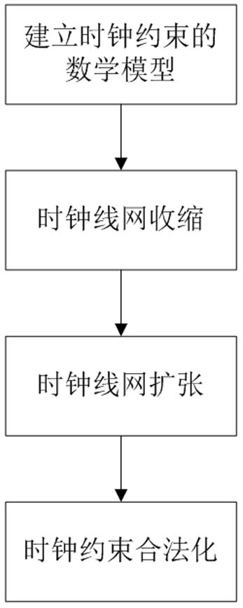
[0026] Such as figure 1 As shown, this embodiment provides a clock legalization method based on heterogeneous FPGA layout, including the following steps:

[0027] (1) Establish a mathematical model of clock constraints.

[0028] The specific implementation method of step (1) is:

[0029] First of all, for the FPGA clock constraints, the following representation is made: with module v i The center coordinates of (x i ,y i ) to represent its position, let C k is the index set of blocks connected by clock k, namely {v i |i∈C k}. Let R be the set of clock regions, j∈R, let Indicates the x-coordinate of the left and right boundaries of clock region j. Indicates the y-coordinates of the upper and lower boundaries of clock region j. When the bounding box of the clock load overlaps with the clock region, the clock is located in t...


PUM


Abstract

The invention relates to a clock legalization method based on heterogeneous FPGA layout. The method comprises the following steps: (1) establishing a clock constrained mathematical model; and (2) based on the established mathematical model, carrying out clock constraint legalization in two steps of clock net contraction and clock net expansion. The method is beneficial to legalization of the clock, and prevents the clock line network from violating the clock constraint in the layout process.

Description

technical field [0001] The invention belongs to the technical field of VLSI physical design automation, and in particular relates to a clock legalization method based on heterogeneous FPGA layout. Background technique [0002] Heterogeneous Field Programmable Gate Array (FPGA) is currently a popular FPGA chip because it can realize multiple functions, has higher performance, and can meet various demands. Correspondingly, its design complexity and scale are also increasing, which brings great challenges to heterogeneous FPGA layout. [0003] The optimization goal of FPGA layout is usually line length, and routability, timing and power consumption will be considered at the same time. In current FPGA designs, there may be hundreds of global clocks. Due to the limited clock routing resources of the current FPGA chip, we need to consider the position of the clock net in the layout phase to avoid the failure of the clock net routing in the routing phase. [0004] The FPGA chip ...

Claims


Application Information

Patent Timeline
Patent Type & Authority Applications(China)
IPC IPC(8): G06F30/34G06F111/04G06F117/04
CPCG06F30/34G06F2111/04G06F2117/04
Inventor 陈建利杨薇林智峰
Owner FUZHOU UNIV
Why Eureka
Try Eureka