
A circuit board printing and placement equipment

A circuit board and equipment technology, applied in the field of circuit board manufacturing equipment, can solve problems such as defective circuit boards, wrong placement of components, and offset welding of components, etc., and achieve the effect of improving the yield rate

Active Publication Date: 2022-04-19
广东万新达电子科技有限公司
View PDF0 Cites 0 Cited by
  • Summary
  • Abstract
  • Description
  • Claims
  • Application Information

AI Technical Summary

Problems solved by technology

[0004] In view of the related technologies mentioned above, the inventor believes that: after the circuit board is printed and patched, the circuit board is immediately transported into the reflow soldering machine for component welding, but it is often found when the soldered components are inspected. Some components have soldering offset or the placement position of components is wrong, which leads to the problem of defective products on the circuit board

Method used


Image

  • A circuit board printing and placement equipment
  • A circuit board printing and placement equipment
  • A circuit board printing and placement equipment

Examples


Embodiment Construction

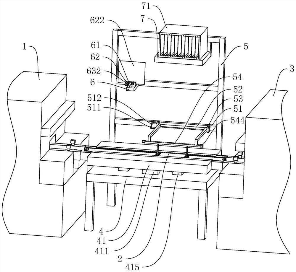
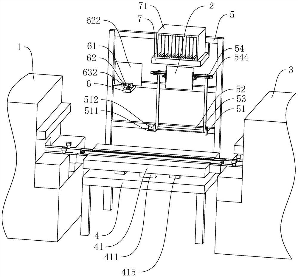
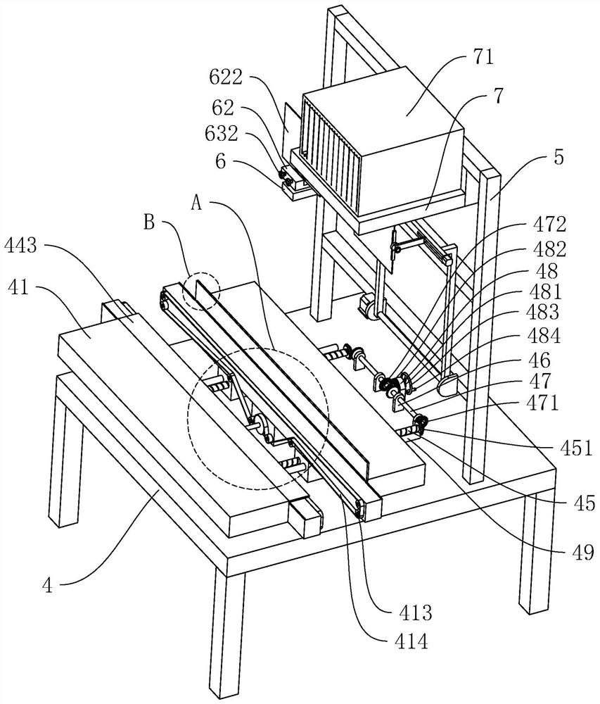
[0041] The following is attached Figure 1-8 The application is described in further detail.

[0042] The embodiment of the present application discloses a circuit board printing and placement equipment. refer to figure 1 and figure 2 The circuit board printing and placement equipment includes a placement machine body 1, the placement machine body 1 is used to print red glue or solder paste coating on the circuit board 2, and then automatically paste the components on the corresponding position of the circuit board 2 , so that the process of printing and patching the circuit board 2 can be realized. And a reflow soldering machine body 3 is fixedly placed on one side of the outlet end of the placement machine body 1, and the reflow soldering machine body 3 can fix and weld the components on the circuit board 2 to improve the stability of the components. After welding, the welding condition of the components welded on the circuit board 2 is detected, and finally the process...


PUM


Abstract

The present application relates to a circuit board printing and placement equipment, including a placement machine body and a reflow soldering machine body arranged on one side of the placement machine body, and an arrangement between the placement machine body and the reflow soldering machine body There is a pre-detection device for inspecting the components on the circuit board. The pre-detection device includes a base arranged between the body of the placement machine and the body of the reflow soldering machine, and the base is symmetrically arranged There is a fixed plate, and a conveying mechanism for conveying the circuit board is arranged between the two fixed plates, and a fixed frame is also arranged on the base, and one side of the fixed frame is provided with a device for carrying out the circuit board. Clamping and swinging mechanism for clamping and swinging. The application can facilitate the pre-detection effect on the circuit board before welding the components, thereby reducing the welding deviation of the components on the circuit board or the wrong patch position of the components, thereby improving the yield rate of the circuit board.

Description

technical field [0001] The present application relates to the field of circuit board manufacturing equipment, in particular to a circuit board printing and placement equipment. Background technique [0002] With the continuous development of science and technology in our country, it is necessary to upgrade the electronic information manufacturing industry and vigorously develop core industries such as integrated circuits, software and new components according to the overall trend of digitization, networking and intelligence. Among them, the PCB circuit board is widely used in various electronic devices, and it is mainly used for integrating electronic device circuits. At the same time, the miniaturization and visualization of the circuit board plays an important role in the mass production of fixed circuits and the optimization of the layout of electrical appliances. [0003] In the process of circuit board processing in the related art, the circuit board is automatically l...

Claims


Application Information

Patent Timeline
Patent Type & Authority Patents(China)
IPC IPC(8): H05K3/34
CPCH05K3/34
Inventor 张剑明程彬左有辉
Owner 广东万新达电子科技有限公司
Learn More