Solar cell crystal silicon wafer series welding machine

A technology for solar cells and crystalline silicon wafers, applied in circuits, electric heating devices, electrical components, etc., can solve problems such as no detection system, low welding efficiency, and low welding yield

Inactive Publication Date: 2013-07-03
深圳市晶拓光伏自动化设备有限公司
View PDF12 Cites 34 Cited by
  • Summary
  • Abstract
  • Description
  • Claims
  • Application Information

AI Technical Summary

Problems solved by technology

However, due to the low degree of automation, the welding efficiency is not hig

Method used


Image

  • Solar cell crystal silicon wafer series welding machine
  • Solar cell crystal silicon wafer series welding machine
  • Solar cell crystal silicon wafer series welding machine

Examples


Embodiment Construction

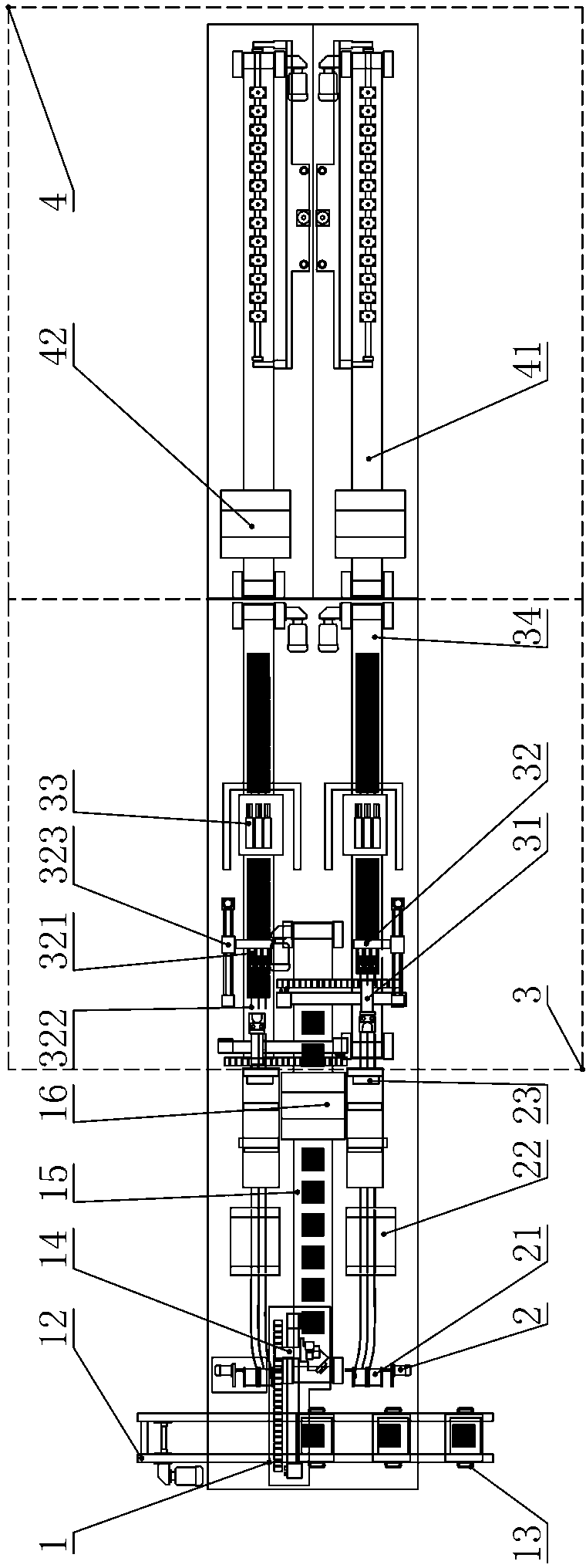
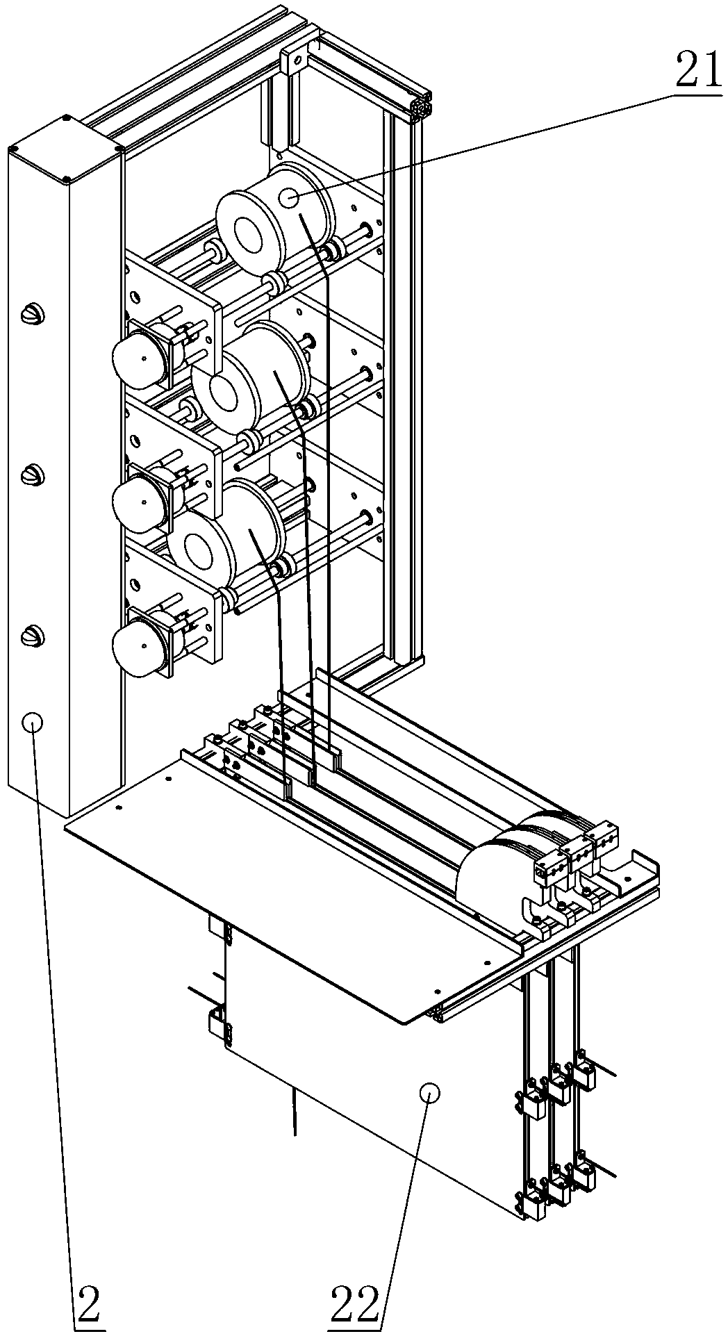
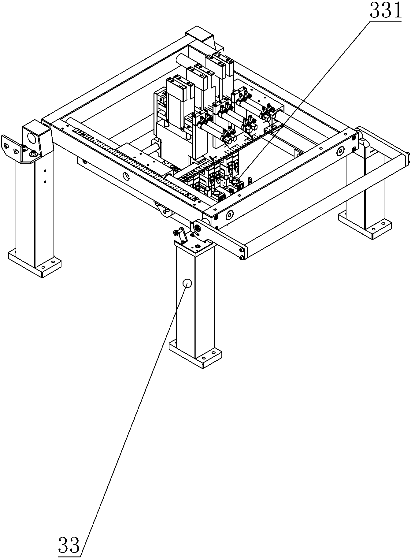
[0022] Such as figure 1 As shown, a solar cell crystalline silicon chip stringer includes a welding mechanism 1, and also includes a welding auxiliary mechanism directly or indirectly connected to the welding mechanism 3, and the welding auxiliary mechanism is an automatic feeding mechanism 1, a welding With feeding mechanism 2 or automatic discharging mechanism 4. The welding mechanism 3 includes a battery piece carrying and conveying unit 34 for supporting the battery pieces, a ribbon pulling unit 32 cooperating with the ribbon feeding mechanism 2 and a welding heating unit arranged above the battery piece carrying and conveying unit 34 Unit 33. The automatic feeding mechanism 1 includes a first conveying unit 12 and a second conveying unit 15, and also includes a picking manipulator 14 arranged between the first conveying unit 12 and the second conveying unit 15 and placed on the The material carrying unit 13 above the first conveying unit 12 . The ribbon pulling unit 32...


PUM


Abstract

The invention discloses a solar cell crystal silicon wafer series welding machine, which comprises a welding mechanism and a welding assisting mechanism which is directly or indirectly connected with the welding mechanism, wherein the welding assisting is an automatic feeding mechanism, a welding strip feeding mechanism or an automatic discharging mechanism. The automatic feeding mechanism, the welding strip feeding mechanism, the welding mechanism and the automatic discharging mechanism are sequentially connected. All mechanisms work cooperatively and can realize the continuous, rapid and stable welding of cells.

Description

technical field [0001] The invention relates to a welding device, in particular to a solar cell crystalline silicon chip stringer. Background technique [0002] As a clean energy source, solar energy is widely used. The main way of solar energy application is solar power generation. Solar panels are an indispensable and important part of solar power generation. Welding battery cells together to make large panels is an important part of the solar panel processing process. In one link, there is an urgent need for a welding equipment with a high degree of automation. The Chinese invention patent with the authorized announcement number CN201744762U disclosed "a semi-automatic solar cell sheet tin-coated ribbon welding machine" on February 16, 2011. The workbench, the front end of the workbench is fixedly equipped with a material strip bracket for supporting the tin-coated strip, the workbench behind the material strip support is fixedly equipped with a feeding device, and the ...

Claims


Application Information

Patent Timeline
IPC IPC(8): B23K3/00B23K3/04B23K3/08H01L31/18
CPCY02P70/50
Inventor 赵梅
Owner 深圳市晶拓光伏自动化设备有限公司
Why Eureka
Try Eureka