
Cylinder lock unit and an associated key

A cylinder lock and key technology, applied in the direction of keys, cylinder marble locks, locks with turning keys, etc., can solve problems such as no security structure.

Active Publication Date: 2021-08-06
WINLOC
View PDF22 Cites 0 Cited by
  • Summary
  • Abstract
  • Description
  • Claims
  • Application Information

AI Technical Summary

Problems solved by technology

[0012] However, in general, there are no cylinder lock units on the market that are really high security and have a compact structure and enough space to possibly accommodate an additional lock assembly in the rear area of ​​the key plug

Method used


Image

  • Cylinder lock unit and an associated key
  • Cylinder lock unit and an associated key
  • Cylinder lock unit and an associated key

Examples


Embodiment Construction

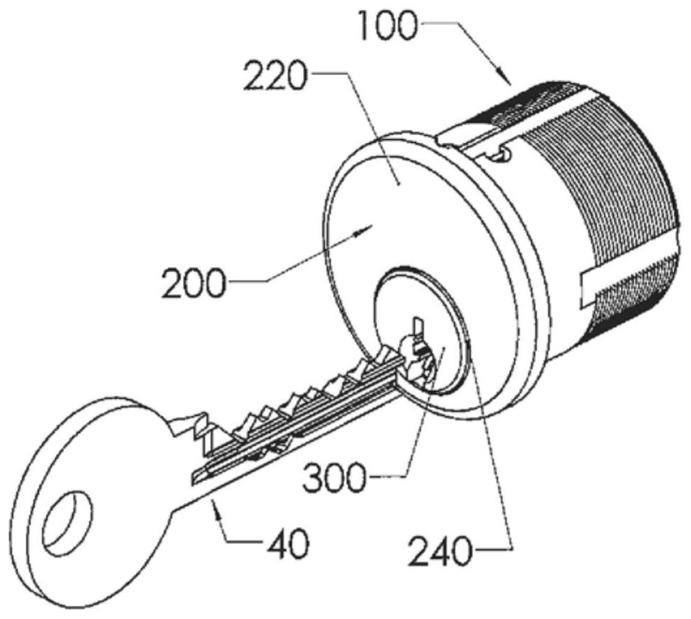
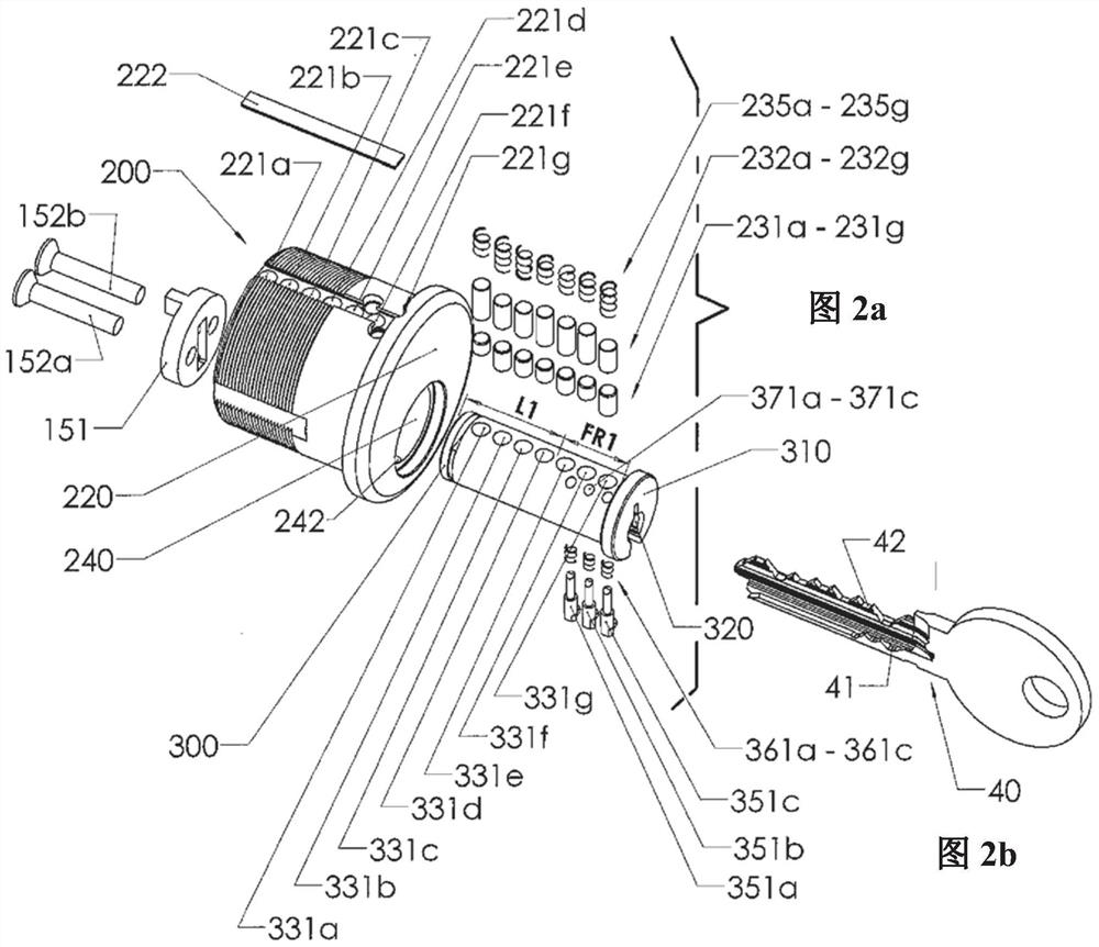
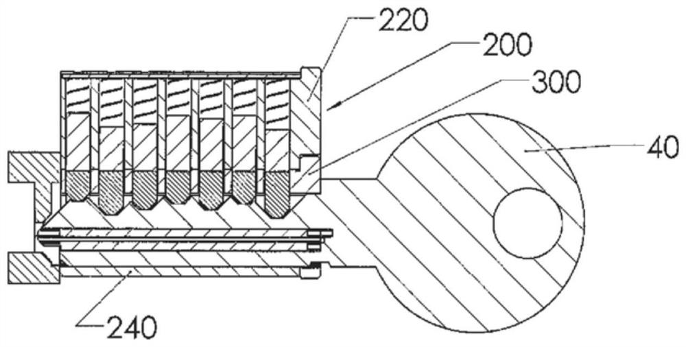
[0053] A first embodiment of the lock unit 100 of the present invention is in figure 1 , Figure 2a , Figure 2b , image 3 , Figure 4 , Figure 5a , Figure 5b , Figure 5c and Figure 5d Shown in , includes a cylindrical housing 200 with a rotatable key plug 300 and an associated key 40 .

[0054] The cylindrical housing 200 has a threaded rear end portion and a slightly tapered front flange.

[0055] As is well known, the lock unit 100 is typically permanently installed in a door or the like in order to cooperate with a door lock mechanism. The cylindrical housing 200 includes an upper solid portion 220 and a lower portion 240 formed with a cylindrical bore receiving a rotatable key plug 300 .

[0056] The rotatable key plunger 300 is formed as a single piece and is adapted to transmit torque to the locking mechanism as the plunger is rotated. In this embodiment, if Figure 2a As shown, this is achieved by a torque transfer connection comprising a cam member 151...


PUM


Abstract

A cylinder lock unit provided with a rotatable key plug (300) and a connection for transferring a torque to a lock mechanism when a key plug is rotated. The cylinder lock unit includes a housing (200) having an upper part (220), provided with a central row of locking pins in associated cavities, and a lower part (240) with a cylindrical bore accommodating the rotatable key plug. A back region (LI) of the key plug has a minimum length of at least 50% of the total length thereof. The adjoining front region (FR1) has a maximum length of 50% of the total length and accommodates, in addition to the central row of locking pins, at least one side locking mechanism (351a, 351b, 351c) which is located in its entirety within the front region of the key plug and interacts with the lower part of the housing. The invention also relates to a key (40) for unlocking the lock unit.

Description

technical field [0001] The invention relates to a cylinder lock unit of the type indicated in the preamble of claim 1 . Thus, the cylinder lock unit comprises a housing with an upper part and a lower part, [0002] said lower part of the housing has a cylindrical bore to accommodate a rotatable key plug, [0003] The rotatable key plug is formed in one piece and is adapted to transmit torque to the locking mechanism through the torque transfer connection when the key plug is rotated, [0004] said upper part of the housing is provided with a central row of upper and lower locking pins in associated chambers, [0005] said key plug has a central row of corresponding cavities for receiving said lower locking pin in said central row, [0006] said key plug having at least one side locking mechanism operates independently of said central row of upper and lower locking pins, [0007] a keyway extends axially rearwardly from the front end of the key plug and is configured to rec...

Claims


Application Information

Patent Timeline
IPC IPC(8): E05B17/04E05B19/00E05B27/00
CPCE05B17/047E05B19/0064E05B27/0039E05B27/0078E05B27/0082
Inventor B·维登
Owner WINLOC
Learn More