
Gas sensor

A gas sensor, porous technology, applied in instruments, scientific instruments, measuring devices, etc., can solve problems such as strength reduction

Pending Publication Date: 2021-08-06
NGK INSULATORS LTD
View PDF12 Cites 0 Cited by
  • Summary
  • Abstract
  • Description
  • Claims
  • Application Information

AI Technical Summary

Problems solved by technology

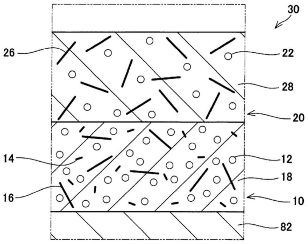
In addition, in the gas sensor of Patent Document 1, as the porosity of the lower layer is increased, the strength of the lower layer decreases, so ceramic fibers are added to the lower layer to cope with the decrease in strength.

Method used


Image

  • Gas sensor
  • Gas sensor
  • Gas sensor

Examples


Embodiment

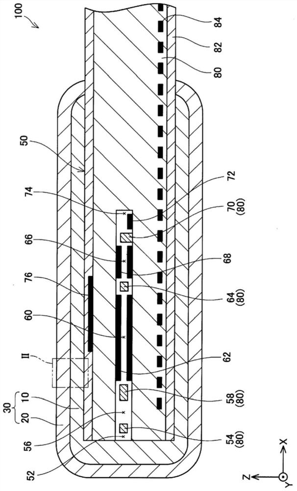
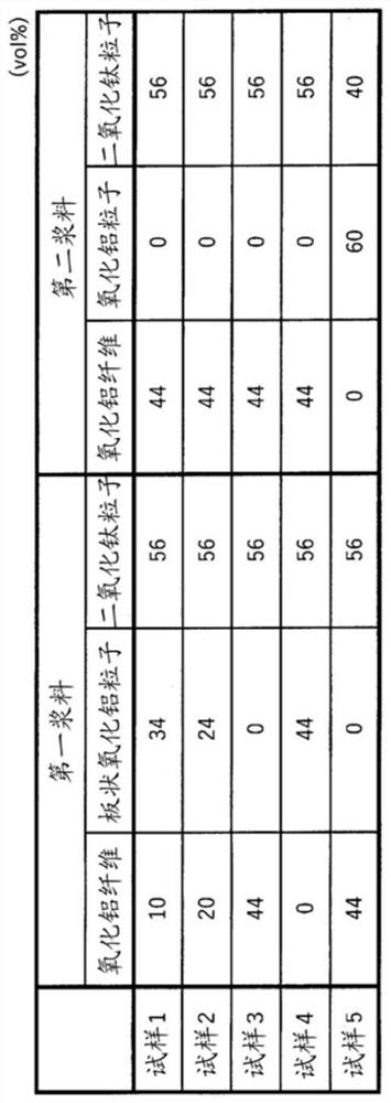
[0044] Five types of gas sensors 100 (samples 1 to 5) having different constituent materials of the porous protective layer 30 were produced, and the characteristics of the gas sensors 100 (porous protective layer 30 ) were evaluated. image 3 The composition of the slurry used to prepare each sample is shown in , Figure 4 The evaluation results of each sample are shown in .

[0045] The porous protective layer 30 is applied to the sensor element 50 by dipping. Specifically, a slurry for the first layer (first slurry) and a slurry for the second layer (second slurry) were prepared, and one end of the sensor element 50 was dipped in the first slurry to form a 300 μm second slurry. layer. Then, the sensor element 50 was placed in a dryer, and the first layer was dried at 200° C. (atmospheric atmosphere) for 1 hour. Next, the portion of the sensor element 50 on which the first layer was formed was dipped in the second slurry to form a 300 μm second layer. Then, the sensor el...


PUM

PropertyMeasurementUnit
Viscosityaaaaaaaaaa

Abstract

This gas sensor is configured so that a porous protective layer is provided to the surface of a sensor element. In the gas sensor, the porous protective layer includes ceramic particles and ceramic fibers. The ceramic fibers are present extending from the obverse surface to the reverse surface of the porous protective layer.

Description

technical field [0001] This specification discloses technologies related to gas sensors. Background technique [0002] There is known a gas sensor in which the surface of a sensor element is protected by a porous protective layer. This gas sensor is arranged, for example, in an exhaust system of a vehicle having an internal combustion engine, and is used to measure the gas concentration of a specific gas contained in exhaust gas. Japanese Unexamined Patent Publication No. 2014-98590 (hereinafter referred to as Patent Document 1) discloses a gas sensor in which a porous protective layer has a two-layer structure. In the gas sensor of Patent Document 1, by making the porosity of the lower layer (the layer in contact with the sensor element) larger than the porosity of the upper layer (the layer exposed in the exhaust gas space), harmful components contained in the exhaust gas, etc. are utilized in a dense ( (lower porosity) upper layer captures and improves the thermal insul...

Claims


Application Information

Patent Timeline
IPC IPC(8): G01N27/416G01N27/409
CPCG01N27/4077G01N27/4075G01N27/409G01N27/416
Inventor 藤崎惠实坪井美香富田崇弘
Owner NGK INSULATORS LTD
Learn More