Illumination device, image display device, and projector
A technology for image display devices and lighting devices, applied in projection devices, optics, instruments, etc., can solve the problems of complexity, increase in device cost, and decrease in light utilization efficiency, and achieve the advantages of suppressing increase, suppressing size increase, and suppressing speckle patterns. Effect
- Summary
- Abstract
- Description
- Claims
- Application Information
AI Technical Summary
Problems solved by technology
Method used
Image
Examples
no. 1 Embodiment
[0138] The first embodiment will be described.
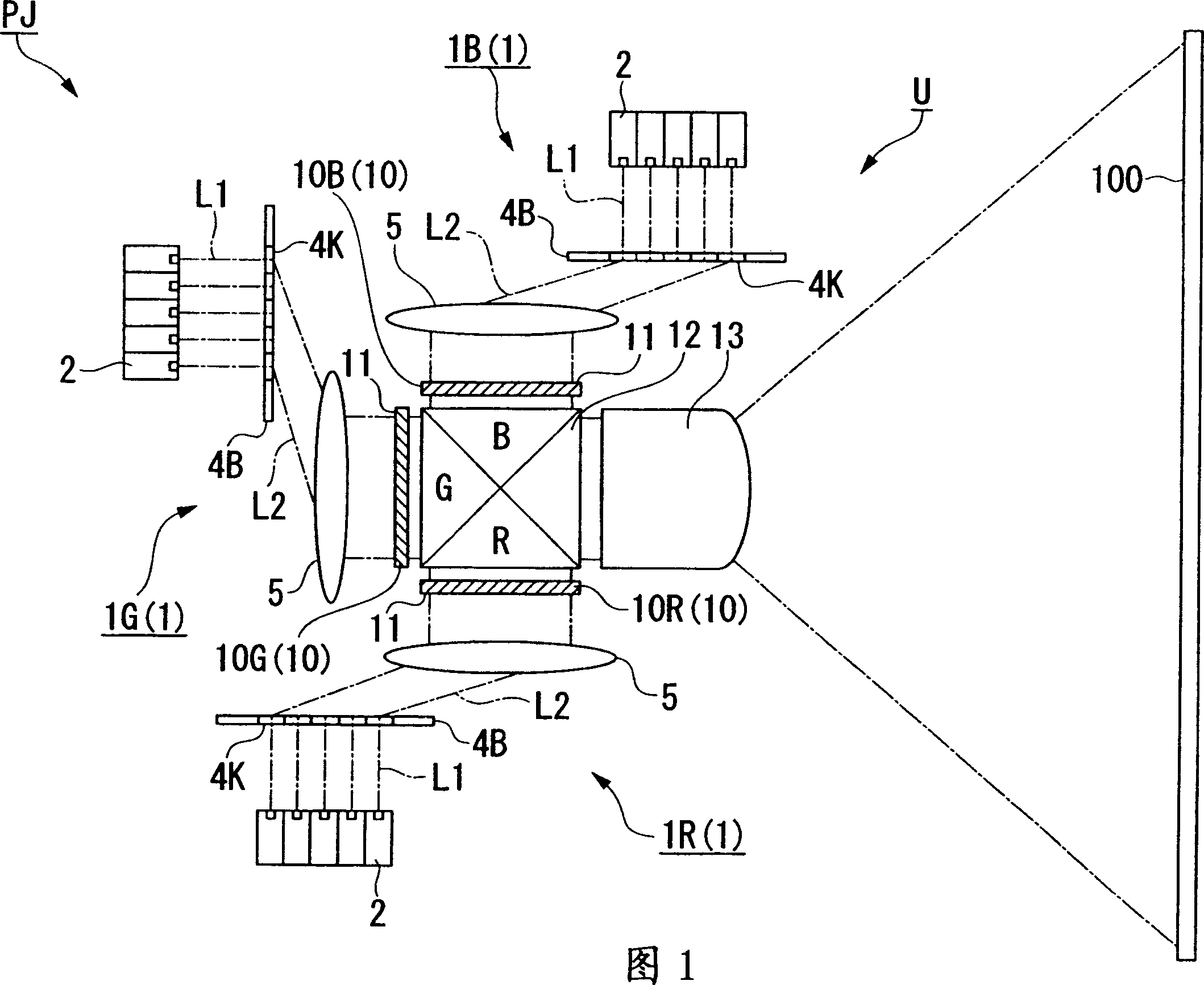
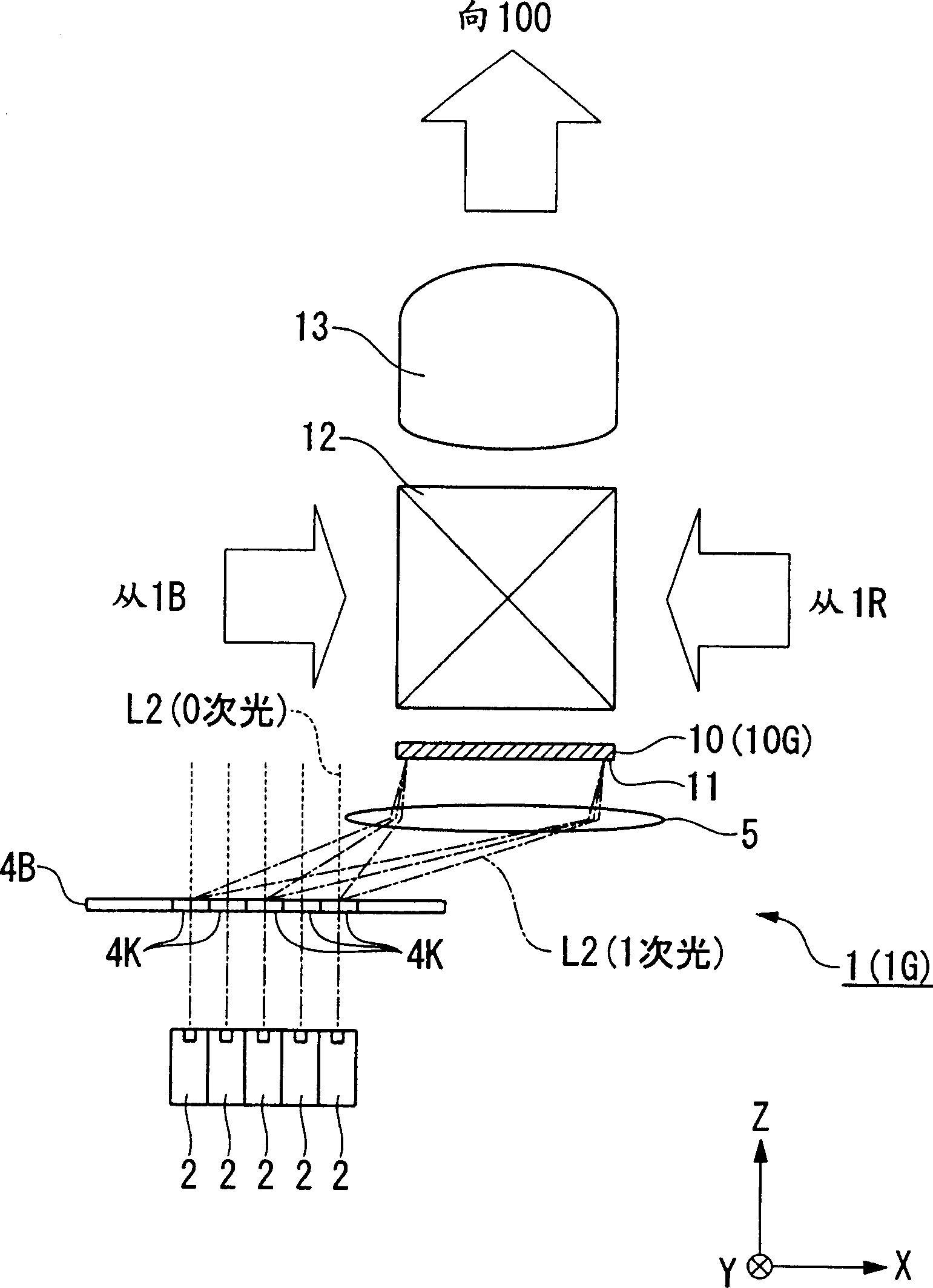
[0139] FIG. 1 is a schematic configuration diagram showing an image display device PJ of a first embodiment, figure 2 It is an enlarged view of the main part of Fig. 1.
[0140] In this embodiment, the image display device is described by taking the following projection type image display device (projector) as an example. In this projection type image display device, through the projection system, the image with The colored light of the image information is projected on the screen.
[0141] In FIG. 1 , projector PJ includes a projection unit U that projects light including image information on a screen 100 (second surface).
[0142] From the projection unit U, light is projected onto the screen 100 , whereby an image is formed on the screen 100 .
[0143] In the projector PJ of this embodiment, the screen 100 is a transmissive screen, and light having image information is projected onto the screen 100 from the front side of t...
no. 2 Embodiment
[0259] refer to Figure 7 The second embodiment will be described.
[0260] In the following description, the same reference numerals are used for the components that are the same as or equivalent to those of the above-mentioned embodiments, and the description thereof is simplified or omitted.
[0261] in the above figure 2 In the above embodiment, the surface (light exit surface) of the diffractive optical element 4K and the incident surface 11 of the spatial light modulation device 10 are arranged substantially in parallel, however, the surface of the diffractive optical element 4K may also be arranged to face in different directions. (light exit surface) and the incident surface 11 of the spatial light modulation device 10 .
[0262] By forming it in this way, it is possible to reduce the size of the device.
no. 3 Embodiment
[0264] Refer below Figure 8 , the third embodiment will be described.
[0265] Figure 8 It is a plan view schematically showing the positional relationship between the spatial light modulation device 10 (incident surface 11 ) and the plurality of laser light source devices 2 .
[0266] picture Figure 8 As shown, the incident surface 11 has a substantially rectangular shape (rectangular shape) in plan view, and has a first side H1 parallel to the Y axis and a second side H2 parallel to the X axis.
[0267] In addition, "planar view" refers to the shape and positional relationship when the surface is viewed from a direction perpendicular to the surface (here, the incident surface).
[0268] That is, "planar view" refers to the shape and positional relationship in the two-dimensional direction along a certain surface.
[0269] Thus, for example, "the incident surface 11 is substantially rectangular when viewed from a plane" means that the incident surface 11 is substantial...
PUM
 Abstract
Description
Claims
Application Information
 - R&D
- Intellectual Property
- Life Sciences
- Materials
- Tech Scout
- Unparalleled Data Quality
- Higher Quality Content
- 60% Fewer Hallucinations
Browse by: Latest US Patents, China's latest patents, Technical Efficacy Thesaurus, Application Domain, Technology Topic, Popular Technical Reports.
© 2025 PatSnap. All rights reserved.Legal|Privacy policy|Modern Slavery Act Transparency Statement|Sitemap|About US| Contact US: help@patsnap.com


