Interlocked brake device for two-wheel motorcycle

A technology of linked brakes and motorcycles, applied in bicycle brakes, bicycle accessories, etc., can solve the problems of high cost, limited layout of parts, and large number of parts

Inactive Publication Date: 2011-07-20
HONDA MOTOR CO LTD
View PDF5 Cites 33 Cited by
  • Summary
  • Abstract
  • Description
  • Claims
  • Application Information

AI Technical Summary

Problems solved by technology

[0005] According to the interlocking brake device described in the aforementioned Patent Document 1, a balanced interlocking brake can be provided, but the number of parts around the pedal increases and becomes complicated, and the layout of the parts tends to be limited.
[0006] On the other hand, the rear wheel brake mechanism is hydraulically operated together with the front wheel brake mechanism. If it is a so-called disc brake type, the periphery of the pedal can be simplified, but there is another problem of high cost.

Method used


Image

  • Interlocked brake device for two-wheel motorcycle
  • Interlocked brake device for two-wheel motorcycle
  • Interlocked brake device for two-wheel motorcycle

Examples


Embodiment Construction

[0062] Hereinafter, embodiments of the interlocking brake device for motorcycles according to the present invention will be described with reference to the drawings.

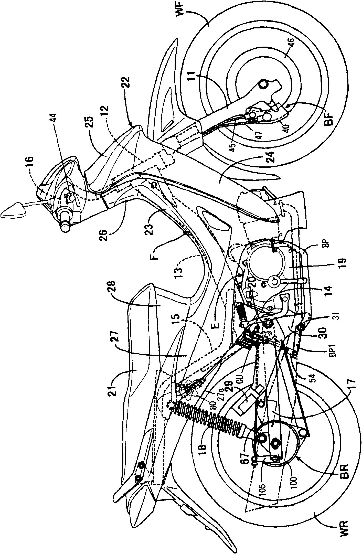
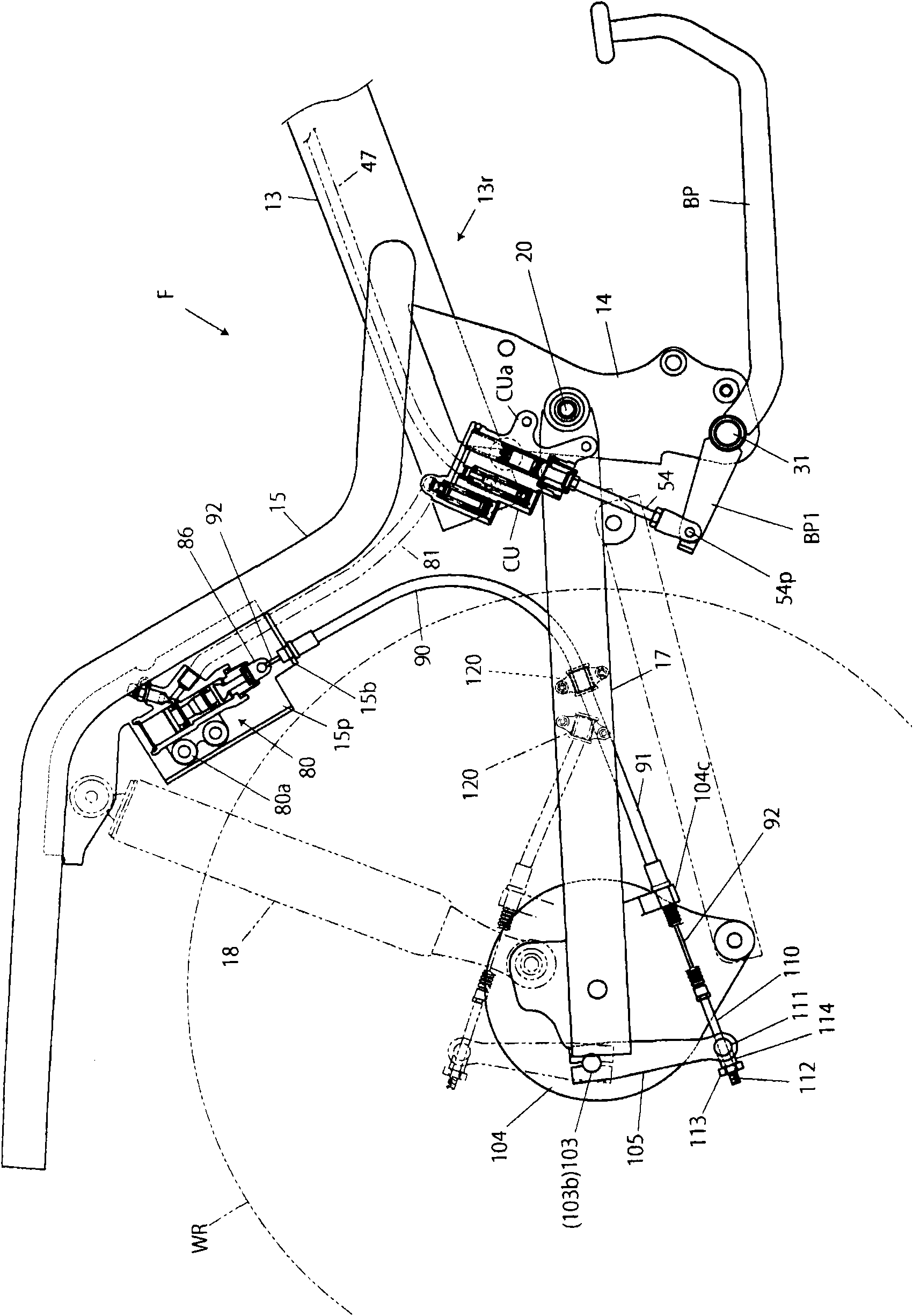
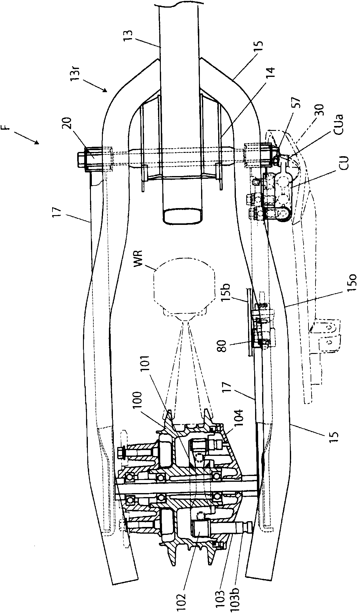
[0063] figure 1 It is a side view showing an example of a motorcycle to which an embodiment of the interlocking brake device for motorcycles according to the present invention is applied, figure 2 It is a side view showing the main part of the frame structure and interlocking brake device of the motorcycle, image 3 It is a plan view showing the frame structure of the motorcycle and the main parts of the interlocking brake device.

[0064] Such as figure 1 As shown, the two-wheeled motorcycle has a body frame F, and the body frame F has: a main frame portion 13 extending downward and rearward from a head pipe 12 that supports a handle 16 in a steerable manner; End 13r (refer to figure 2 ) the rear frame portion 15 extending upward and rearward; the pivot frame portion 14 extending downward from the rear en...


PUM


Abstract

The present invention provides an interlocked brake device for a two-wheel motorcycle. Not only is a hydraulic front wheel brake mechanism and a mechanical back wheel brake mechanism adopted, but also a structure at the periphery of a pedal is simplified. The interlocked brake device is provided with the following components: a back carriage part (15) which extends upwards from a back end of a main carriage part (13); a pivot carriage part (14) which extends downwards from a back end of the main carriage part (13); a back drum type brake (BR) which brakes a back wheel; a front disc type brake(BF) which brakes a front wheel (WF); a main hydraulic cylinder (CU) which is interlocked with the operation of a brake pedal (BP) for generating a braking force that is applied to the back drum typebrake (BR) and the front disc type brake (BF); a front tube which transmits a hydraulic force generated by the motion of the main hydraulic cylinder to the front disc type brake (BF); and auxiliary hydraulic cylinder (80) which transmits the hydraulic force generated by the motion of the main hydraulic cylinder through the back tube and functions thereby; and a mechanical transmission component which is used for transmitting the output of the auxiliary hydraulic cylinder (80) to the back drum type brake (BR), wherein the auxiliary hydraulic cylinder (80) is supported on the back carriage part(15).

Description

technical field [0001] The invention relates to an interlocking braking device for a two-wheeled motorcycle. Background technique [0002] Conventionally, a so-called interlocking braking device is known, which can provide braking force to the rear wheel braking device by operating the brake pedal, and can also provide braking force to the front wheel braking device in conjunction (for example, Patent Document 1). . [0003] 13 and 14 in Patent Document 1, the interlocking brake device operates the brake pedal 21 to activate the rear wheel brake through the brake rod 23C, and through the reaction force transmission mechanism 26D (torque rod) pushes the main hydraulic cylinder M2 to generate hydraulic pressure and also make the front wheel brake work. [0004] Patent Document 1: Japanese Patent Laid-Open No. 2006-62559 [0005] According to the interlocking brake device described in Patent Document 1, a balanced interlocking brake can be provided, but the number of parts a...

Claims


Application Information

Patent Timeline
Patent Type & Authority Applications(China)
IPC IPC(8): B62L3/04B62L3/08
Inventor 斋藤聪田中敬深
Owner HONDA MOTOR CO LTD
Why Eureka
Try Eureka