
Anti-drift apparatus of device in microgravity environment and device

A microgravity, anti-drift technology, applied in the direction of quick-acting fasteners, bolts, etc., can solve the problems of mission failure, the anti-drift device has not been verified on-orbit, and the formation of space junk

Active Publication Date: 2021-08-10
TECH & ENG CENT FOR SPACE UTILIZATION CHINESE ACAD OF SCI
View PDF7 Cites 2 Cited by
  • Summary
  • Abstract
  • Description
  • Claims
  • Application Information

AI Technical Summary

Problems solved by technology

[0002] The anti-floating locking device in the microgravity environment is generally used in the field of manned spaceflight. When the equipment needs to be operated, repaired and replaced by astronauts on orbit, especially when the maintenance and replacement of extravehicular equipment is required, the astronauts use tools to tighten the fastening screws (device) of the equipment. ) is released, the device will be affected by the initial acceleration in the microgravity environment, and there is a risk of drifting away, causing the risk of equipment loss in space, mission failure, and formation of space junk, which will affect the safety of spacecraft and astronauts. In order for the personnel to complete the on-orbit maintenance and replacement work more reliably, it is necessary to take corresponding anti-floating and installation and positioning measures for the equipment to be repaired and replaced.
[0003] At present, the anti-drifting devices used in the on-orbit maintenance and replacement of my country's space products have basically not passed the on-orbit verification.

Method used


Image

  • Anti-drift apparatus of device in microgravity environment and device
  • Anti-drift apparatus of device in microgravity environment and device
  • Anti-drift apparatus of device in microgravity environment and device

Examples


Embodiment 1

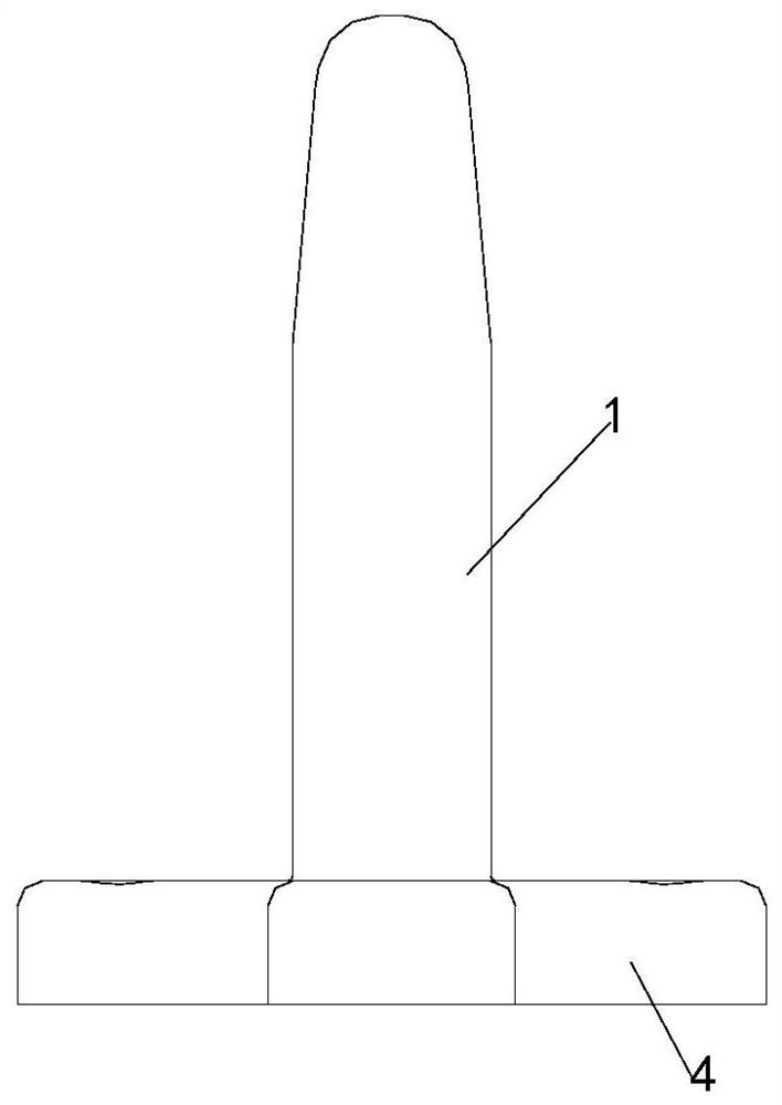
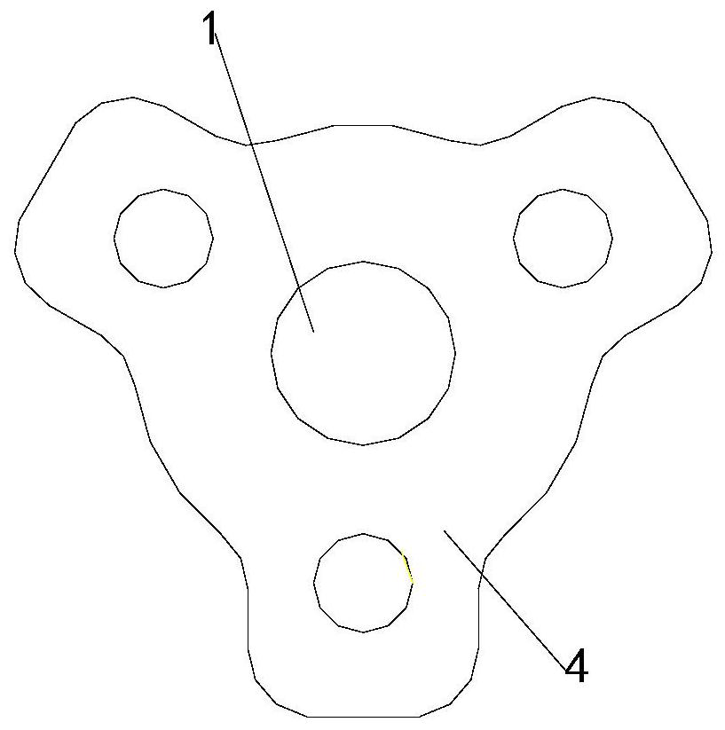
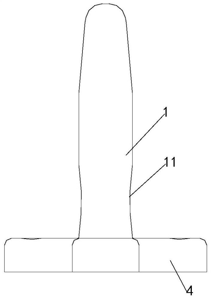
[0052] Such as Figure 1a-Figure 10 As shown, an anti-floating device for equipment in a microgravity environment includes an anti-floating component and a guiding and positioning component. The anti-floating component includes a locking pin 1 and an anti-floating guide sleeve 2. There is a locking through hole 21, and the locking pin 1 can be axially moved and inserted in the locking through hole 21; the guide positioning assembly includes a guide sleeve 6 and a guide pin 5, and the guide sleeve 6 is provided with a guide through hole, and the guide pin 5 can be axially moved and inserted in the guide through hole; the height of the guide pin 5 is greater than the height of the locking pin 1 .

[0053] Wherein, the locking pin 1 and the guide pin 5 of this embodiment may be of a cylindrical structure or a polygonal prism structure, etc., and the locking through hole 21 and the guiding through hole may be of suitable round holes or polygonal holes.

[0054] In this embodiment, ...

Embodiment 2

[0057] Such as Figure 1a-Figure 10 As shown, an anti-floating device for equipment in a microgravity environment includes an anti-floating component and a guiding and positioning component. The anti-floating component includes a locking pin 1 and an anti-floating guide sleeve 2. There is a locking through hole 21, and the locking pin 1 can be axially moved and inserted in the locking through hole 21; the guide positioning assembly includes a guide sleeve 6 and a guide pin 5, and the guide sleeve 6 is provided with a guide through hole, and the guide pin 5 can be axially moved and inserted in the guide through hole; the height of the guide pin 5 is greater than the height of the locking pin 1 .

[0058] Wherein, the locking pin 1 and the guide pin 5 of this embodiment may be of a cylindrical structure or a polygonal prism structure, etc., and the locking through hole 21 and the guiding through hole may be of suitable round holes or polygonal holes.

[0059] Such as Figure 6...

Embodiment 3

[0069] Such as Figure 1a-Figure 10 As shown, an anti-floating device for equipment in a microgravity environment includes an anti-floating component and a guiding and positioning component. The anti-floating component includes a locking pin 1 and an anti-floating guide sleeve 2. There is a locking through hole 21, and the locking pin 1 can be axially moved and inserted in the locking through hole 21; the guide positioning assembly includes a guide sleeve 6 and a guide pin 5, and the guide sleeve 6 is provided with a guide through hole, and the guide pin 5 can be axially moved and inserted in the guide through hole; the height of the guide pin 5 is greater than the height of the locking pin 1 .

[0070] Wherein, the locking pin 1 and the guide pin 5 of this embodiment may be of a cylindrical structure or a polygonal prism structure, etc., and the locking through hole 21 and the guiding through hole may be of suitable round holes or polygonal holes.

[0071] Such as Figure 6...


PUM


Abstract

The invention relates to an anti-drift apparatus of a device in a microgravity environment and the device. The anti-drift apparatus comprises an anti-drift assembly and a guide positioning assembly; the anti-drift assembly comprises a locking pin and an anti-drift guide sleeve; the anti-drift guide sleeve is provided with a locking through hole; the locking pin can be inserted into the locking through hole in an axial movement manner; the guide positioning assembly includes a guide sleeve and a guide pin, a guide through hole is formed in the guide sleeve, and the guide pin can be inserted into the guide through hole in an axial movement mode; and the height of the guide pin is greater than that of the locking pin. According to the invention, the anti-drift assembly and the guide positioning assembly are combined for use, so that the positioning, guide and anti-drift functions are achieved; coarse positioning of the device is implemented through the guide positioning assembly, and at the moment, the device can rotate with the axis of the guide pin as the axis, or can horizontally move in the axial direction of the guide pin. The guide pin guides the device to be further installed with the anti-drift assembly (the height of the guide pin is greater than that of the locking pin), and at the moment, fine positioning is finished by the anti-drift guide sleeve on the device and the locking pin.

Description

technical field [0001] The invention relates to the technical field related to the microgravity environment, in particular to an anti-floating device and equipment in the microgravity environment. Background technique [0002] The anti-floating locking device in the microgravity environment is generally used in the field of manned spaceflight. When the equipment needs to be operated, repaired and replaced by astronauts on orbit, especially when the maintenance and replacement of extravehicular equipment is required, the astronauts use tools to tighten the fastening screws (device) of the equipment. ) is released, the device will be affected by the initial acceleration in the microgravity environment, and there is a risk of drifting away, causing the risk of equipment loss in space, mission failure, and formation of space junk, which will affect the safety of spacecraft and astronauts. In order for the personnel to complete the on-orbit maintenance and replacement work more r...

Claims


Application Information

Patent Timeline
IPC IPC(8): F16B21/08F16B19/02
CPCF16B21/08F16B19/02
Inventor 杨雷乔志宏王珂于梦溪
Owner TECH & ENG CENT FOR SPACE UTILIZATION CHINESE ACAD OF SCI
Learn More