A kind of manufacturing die structure of rubber buffer ring

A buffer ring and compression molding technology, which is applied to household appliances, household components, other household appliances, etc., can solve the problems of mass production of unfavorable rubber buffer rings, direct removal of rubber edges, and labor-intensive work to remove rubber edges.

Active Publication Date: 2021-09-14
南通峰帆运动用品有限公司
View PDF5 Cites 0 Cited by
  • Summary
  • Abstract
  • Description
  • Claims
  • Application Information

AI Technical Summary

Problems solved by technology

[0004] In the above-mentioned patents, when the molding work is carried out, there will be glue edges at the pressing position of the upper mold and the lower mold. These glue edges cannot be removed directly during the molding work, and need to be manually removed later, and the work of removing the glue edges is extremely labor-intensive. , which is not conducive to the mass production of rubber buffer rings

Method used


Image

  • A kind of manufacturing die structure of rubber buffer ring
  • A kind of manufacturing die structure of rubber buffer ring
  • A kind of manufacturing die structure of rubber buffer ring

Examples


Embodiment 1

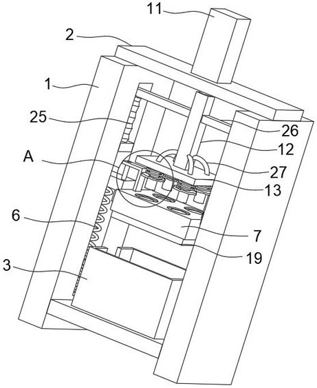
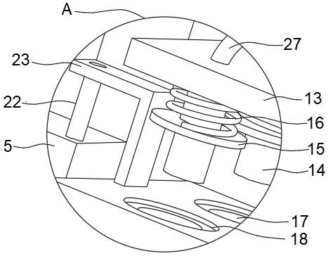
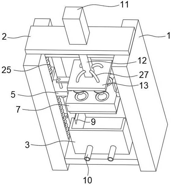
[0030] refer to Figure 1-7 , a die structure for making a rubber buffer ring, comprising two support plates 1 arranged opposite to each other on the left and right, the upper ends of the two support plates 1 are jointly fixedly connected to the installation plate 2, and a cooling water tank 3 is arranged between the two support plates 1 for cooling The water tank 3 is equipped with cooling water, which is used for rapid cooling and forming of the rubber buffer ring after compression molding. The opposite sides of the two support plates 1 are provided with chute 4, and the two chute 4 are slidingly connected with moving blocks 5, each A first spring 6 is fixedly connected between the moving block 5 and the inner bottom wall of the chute 4, and a mold block 7 is fixedly connected between the two moving blocks 5, and the mold block 7 can be moved under the action of the two moving blocks 5. Moving up and down along the chute 4, there are grooves 9 on both sides of the upper end ...

Embodiment 2

[0037] Compared with Embodiment 1, the improvement of this embodiment is that a fixed block 24 is fixedly connected in the two chutes 4 and above the moving block 5, and an air bag 25 is fixedly connected to the upper end of the fixed block 24, and the air bag 25 is used to absorb and exhaust air, both sides of the steel pipe fitting 12 are fixedly welded with connecting pipe fittings 26, and the ends of the two connecting pipe fittings 26 away from the steel pipe fitting 12 extend to the upper end of the corresponding air bag 25 and are fixedly connected with it, and can be fixedly connected to it by a hydraulic cylinder 11 When driving the steel pipe fitting 12 to move down, utilize the connecting pipe fitting 26 to press down the air bag 25; Cut off the rubber edge, a plurality of air holes 28 are provided in the circular groove, and the air holes 28 are used to discharge air. On the steel pipe fitting 12 and below the connecting pipe fitting 26, there are four arc-shaped pi...


PUM


Abstract

The invention discloses a die structure for making a rubber buffer ring, which comprises two support plates, the upper ends of the two support plates are fixedly connected to the installation plate, a cooling water tank is arranged between the two support plates, and the two support plates The opposite side of the support plate is provided with a chute, and a moving block is slidably connected in the two chute, and a first spring is fixedly connected between each moving block and the inner bottom wall of the chute. A mold block is fixedly connected between the moving blocks, and four mold grooves are formed on the mold block, and an annular groove is formed on the inner wall at the upper end of each mold groove. The advantages are: the invention has a high degree of automation, can automatically carry out the molding work of the rubber buffer ring, and at the same time automatically and effectively remove the rubber edge of the product, has low manufacturing cost, greatly saves labor, and improves the production efficiency of the rubber buffer ring.

Description

technical field [0001] The invention relates to the technical field of making rubber buffer rings, in particular to a die structure for making rubber buffer rings. Background technique [0002] The rubber buffer ring is used as a buffer part and is widely used on the idler roller of the belt conveyor. During the production process of the rubber buffer ring, it is usually necessary to use a die structure to form the rubber buffer ring. [0003] After searching, the Chinese Patent Publication No. CN201610716375.7 discloses a rubber buffer ring compression mold, including a cylinder, a ferrule, an upper mold and a lower mold, and the cylinder, ferrule, upper mold and lower mold are surrounded by rubber The mold cavity formed by the buffer ring, the upper mold and the lower mold are arranged oppositely, the cylinder protrudes upward from the top surface of the lower mold, the ferrule is set on the outside of the cylinder and supported between the upper mold and the lower mold, t...

Claims


Application Information

Patent Timeline
Patent Type & Authority Patents(China)
IPC IPC(8): B29C43/36B29C43/32B29C43/52B29C33/72B29C37/02
CPCB29C33/72B29C37/02B29C43/32B29C43/36B29C43/52B29L2031/721
Inventor 秦义忠
Owner 南通峰帆运动用品有限公司
Why Eureka
Try Eureka