Gas collecting and sampling device

A sampling device and gas technology, applied in the field of gas collection and sampling devices, can solve the problems of sampling gas concentration variation, low sampling gas concentration, interference with detection data, etc., and achieve the effects of reducing impact, convenient detection, and convenient sealing

Active Publication Date: 2021-08-17
SHENZHEN ENVIRONMENTAL MONITORING CENT +1
View PDF5 Cites 0 Cited by
  • Summary
  • Abstract
  • Description
  • Claims
  • Application Information

AI Technical Summary

Problems solved by technology

[0003] will use the sampling cylinder to sample the gas. The existing sampling cylinder is composed of a complete cylinder and connecting pipes on both sides. When using it, you need to first After rinsing the sampling cylinder, insert the connector of the inlet pipe into the inlet valve of the sampling point, connect the outlet pipe to the outlet valve of the sampling point, open the safety valves on both sides, and open the valve of the sampling point. Introduce the gas for -min, then close the outlet valve of the sampling point and the safety valve of the outlet pipe, take a sample for -min, then close all the valves, remove the joint, the cylinder is sampled, and the air pressure in the cylinder cannot be obtained directly during sampling. , usually add a barometer directly inside the cylinder, however, the barometer can only monitor the air pressure in the cylinder, when the outlet valve is not opened, the sampled gas may contain air, resulting in changes in the concentration of the sampled gas, and during the sampling process, cannot Directly observe whether the gas inside the cylinder is in a flowing state, that is, it is impossible to determine whether the gas in the cylinder has been replaced, which will easily lead to low sampling gas concentration and interfere with the later detection data

Method used


Image

  • Gas collecting and sampling device
  • Gas collecting and sampling device
  • Gas collecting and sampling device

Examples


Embodiment Construction

[0024] The following will clearly and completely describe the technical solutions in the embodiments of the present invention with reference to the accompanying drawings in the embodiments of the present invention. Obviously, the described embodiments are only some, not all, embodiments of the present invention. Based on the embodiments of the present invention, all other embodiments obtained by persons of ordinary skill in the art without making creative efforts belong to the protection scope of the present invention.

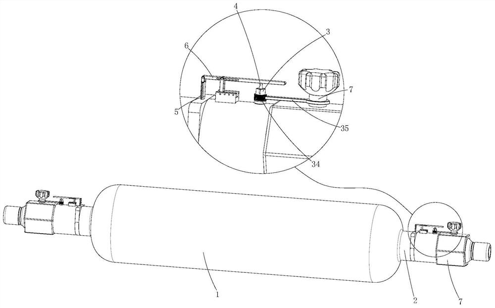
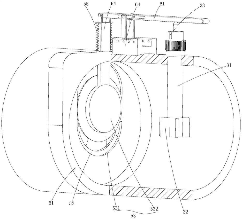
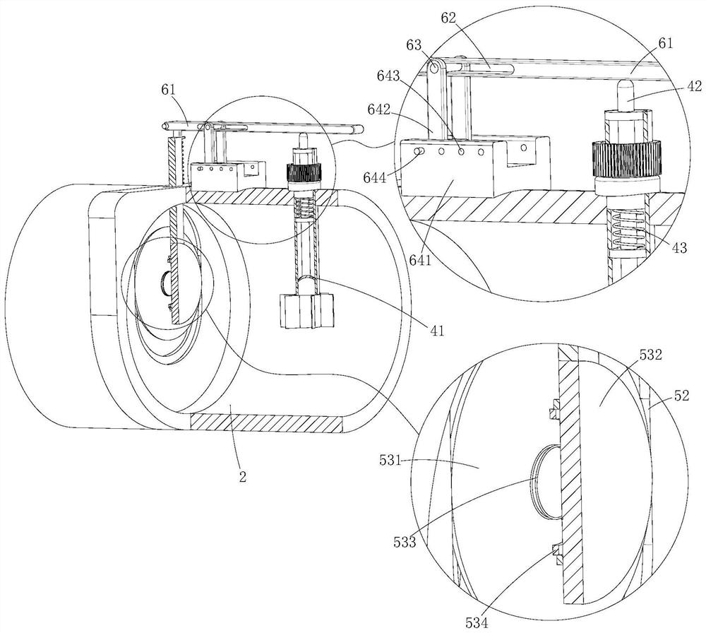
[0025] see Figure 1-3 , the present invention provides a technical solution: a gas collection and sampling device, comprising:

[0026] A bottle body 1, the bottle body 1 collects and stores the gas;

[0027] The connecting pipe 2 is installed at both ends of the bottle body 1. The connecting pipe 2 is fixedly connected with the bottle body 1. The connecting pipe 2 communicates with the inside of the bottle body 1. One of the connecting pipes 2 is an air inl...


PUM


Abstract

The invention discloses a gas collecting and sampling device, comprising: a bottle body for collecting and storing gas; connecting pipes installed at the two ends of the bottle body, wherein one connecting pipe is an air inlet pipe, the other connecting pipe is an air outlet pipe, and the two connecting pipes are sealed through valves; a display mechanism mounted in the connecting pipe, wherein the display mechanism can display the flow of the gas in the bottle body after the valve is opened; a pressure measuring mechanism installed in the display mechanism. Through ascending and descending of the pressure measuring mechanism, the gas flowing state and gas pressure change in the bottle body can be visually observed through the display mechanism and the gas pressure mechanism, the influence of air on the gas concentration is reduced, and later data detection is facilitated. The sealing mechanism is controlled by the pressure measuring mechanism and the transmission part to preliminarily seal the bottle body, the bottle body is conveniently sealed after being filled with gas through air pressure autonomous control, it is guaranteed that the air pressure in the bottle body is at the to-be-measured air pressure, and the bottle body is conveniently used.

Description

technical field [0001] The invention relates to the technical field of gas collection and sampling, in particular to a gas collection and sampling device. Background technique [0002] Gas collection and sampling is the process of collecting pollutant samples in the atmosphere or polluted air samples. There are two types of collection methods: one is to pass a large amount of air through a liquid absorbent or a solid adsorbent to enrich the pollutants with a lower concentration in the atmosphere The other is to use containers (glass bottles, plastic bags, etc.) to collect air containing pollutants. The former measures the average concentration of pollutants in the atmosphere during the sampling time; the latter What is measured is the instantaneous concentration or the average concentration in a short period of time. [0003] Sampling cylinders are used for gas sampling. The existing sampling cylinders are composed of a complete cylinder and connecting pipes on both sides. ...

Claims


Application Information

Patent Timeline
Patent Type & Authority Applications(China)
IPC IPC(8): G01N1/22
CPCG01N1/22
Inventor 罗澍侯化明
Owner SHENZHEN ENVIRONMENTAL MONITORING CENT
Why Eureka
Try Eureka