
A loudspeaker for emergency room

A loudspeaker and emergency room technology, which is applied in the field of loudspeakers in the emergency room, can solve the problems of low crowd efficiency and the inability to guarantee the same side of the crowd to dodge, and achieve the effect of high crowd efficiency

Inactive Publication Date: 2021-11-30
钱程
View PDF16 Cites 0 Cited by
  • Summary
  • Abstract
  • Description
  • Claims
  • Application Information

AI Technical Summary

Problems solved by technology

[0005] The embodiment of the present application provides a loudspeaker for the emergency room, which solves the technical problem in the prior art that the efficiency of evacuating the crowd on the route of the stretcher is low and it is impossible to ensure that the crowd dodges to the same side in the narrow passage when transferring the emergency patient. Realized the technical effect of evacuating the crowd on the route of the stretcher vehicle when transferring emergency patients with high efficiency and effectively dredging out a better traffic route

Method used


Image

  • A loudspeaker for emergency room
  • A loudspeaker for emergency room
  • A loudspeaker for emergency room

Examples


Embodiment 1

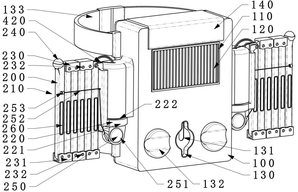
[0081] Such as figure 1 As shown, the speaker used in the emergency room of the present application includes a speaker housing 100, a soft rod assembly 200, a power assembly and a control unit 500;

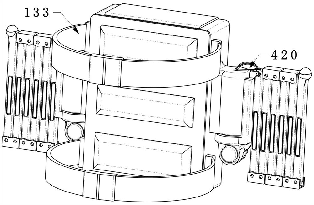
[0082] The loudspeaker housing 100 is a box structure for supporting and positioning the housing sound outlet 110, the sound generating unit 120, the housing positioning component 130 and the energy input component 140; the housing sound outlet 110 is positioned at The side wall of the speaker housing 100 is used to output the sound generated by the sound generating unit 120; the sound generating unit 120 is fixed inside the speaker housing 100 for emitting For the effect of the sound of the evacuation crowd, preferably, the sound generating unit 120 has a sound recording function, which is a prior art, and will not be described in detail here; the housing positioning component 130 is arranged on the speaker housing 100, It is used to wear the speaker on the person, hang it on th...

Embodiment 2

[0102] Considering that although the soft rod assembly 200 in the above-mentioned embodiment will not cause greater damage to people who do not evade in time on the passage due to its material, it will accumulate elastic potential energy when it is bent under force, and when it crosses obstacles (people on the passage) ) will release elastic potential energy (rebound), the rebound process is equivalent to doing a whipping action, which is likely to cause damage to other people in the passage; especially children in the passage may cause damage to their heads and even glasses;

[0103] In view of the above problems, the embodiment of the present application adds a rod body anti-rebound component 300 and a rod body restoration component 400 on the basis of the above embodiments to prevent the soft rod assembly 200 from rebounding rapidly after being stressed;

[0104] Specifically:

[0105] Such as Figure 6 to Figure 8 As shown, the soft rod unit 210 is a hollow rod; the rod b...


PUM


Abstract

The present application discloses a loudspeaker used in an emergency room, which includes a loudspeaker housing, a sound generating unit is positioned inside the loudspeaker housing, and a soft rod assembly; the soft rod assembly is positioned on the loudspeaker housing; the soft rod assembly is positioned on the loudspeaker housing; The rod assembly includes a soft rod unit, a soft rod positioning component, a soft rod unit combination component and a soft rod converging component; the soft rod unit is a rod body, the number is multiple, and the material is soft solid. The soft rod unit combination components are combined into W-like rods or telescopic rods, and the lateral length of the combined rods can be adjusted; the soft rod positioning components position the combined rods on the speaker housing; A force is applied to the rod unit to change the lateral length of the combined rod; it realizes the technical effect of high efficiency in evacuating the crowd on the route of the stretcher when transferring emergency patients and effectively dredging out a better traffic route.

Description

technical field [0001] The invention relates to the technical field of loudspeakers, in particular to a loudspeaker used in an emergency room. Background technique [0002] In the emergency room (emergency center), it is often necessary to rescue patients. Some of the patients who need to be rescued come from the ward, and the other part comes from outside the hospital (pulled by an ambulance, etc.). There are many and some aisles are noisy. Patients to be rescued are easily blocked due to crowd blocking. It is extremely difficult to quickly transfer patients. It is necessary to use loudspeakers (megaphones) to continuously broadcast reminders to break through the crowd to a certain extent and let the passage go smoothly. transfer of patients. [0003] Loudspeakers in the prior art are usually fixed on stretchers or worn by medical staff. When transferring patients, they play "please avoid" and other sounds to make people in the passage actively avoid; but in actual use, of...

Claims


Application Information

Patent Timeline
Patent Type & Authority Patents(China)
IPC IPC(8): H04R1/02
CPCH04R1/02
Inventor 钱程吴明
Owner 钱程
Learn More