
Automatic riveting machine for continuous stamping

A riveting machine and automatic technology, applied in the field of riveting machines, can solve the problems of rivet punching offset, inability to fit effectively, etc.

Inactive Publication Date: 2021-04-23
曾爱民
View PDF0 Cites 0 Cited by
  • Summary
  • Abstract
  • Description
  • Claims
  • Application Information

AI Technical Summary

Problems solved by technology

[0005] In order to solve the above-mentioned technology, when using the rivet machine to embed the rivet into the bending corner of the workpiece to fix the inner and outer end surfaces of the fixed object, because the bending corner of the rectangular outer contour of the workpiece is in the shape of a sharp cone, and the pair of rivets of the rivet machine The fixed end of the rivet machine is designed in a round tube shape, so that the fixed end of the rivet machine cannot be effectively fitted to the rectangular bending corner of the workpiece, which makes it easy to cause the stamping deviation of the rivet due to the lack of fit between the two during the stamping process. shifting problem

Method used


Image

  • Automatic riveting machine for continuous stamping
  • Automatic riveting machine for continuous stamping
  • Automatic riveting machine for continuous stamping

Examples


Embodiment 1

[0025] as attached figure 1 To attach Figure 5 Shown:

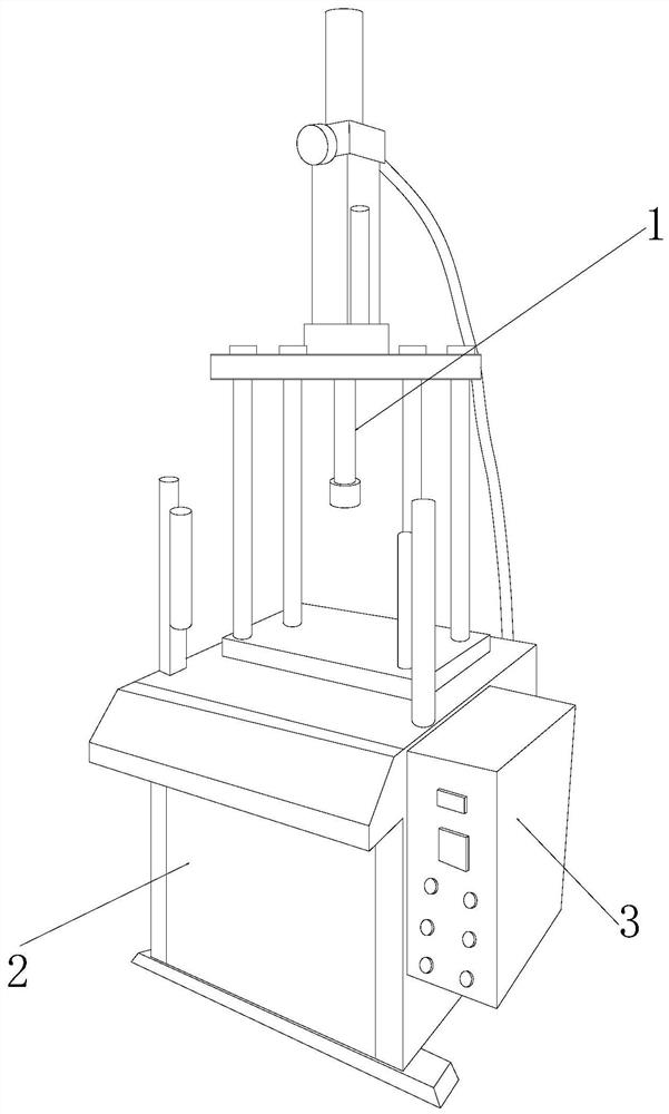
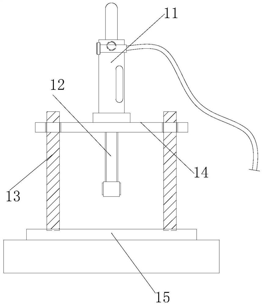
[0026] The invention provides an automatic riveting machine for continuous stamping, the structure of which includes a stamping device 1, a body 2, and a control box 3. A control box 3 is embedded and installed, and the control box 3 is located directly below the stamping equipment 1; the stamping equipment 1 includes a hydraulic device 11, a stamping rod 12, a lifting column 13, a movable plate 14, and a fixed platform 15. The device 11 is inlaid directly above the stamping rod 12, and the stamping rod 12 is embedded and installed directly above the fixed platform 15. The lifting column 13 is inlaid on the inner surface of the left and right ends of the movable plate 14. The movable plate 14 The inlay is installed directly above the fixed platform 15 , and the fixed platform 15 is located directly below the hydraulic unit 11 .

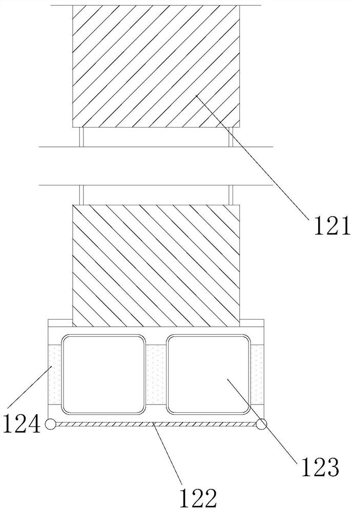
[0027] Wherein, the stamping rod 12 includes a vibrating rod 121, a wrapping mechanism 12...

Embodiment 2

[0032] as attached Figure 5 To attach Figure 7 Shown:

[0033] Wherein, the movable mechanism 221 includes a bidirectional shaft 211, a rubber wrapping sheet 212, an adsorption mechanism 213, and a second hollow block 214. The bidirectional shaft 211 is movably engaged on the inner upper end surface of the movable mechanism 221, and the rubber wrapping sheet 212 Fitted and wrapped on the outer end surface of the bidirectional shaft 211, the adsorption mechanism 213 is embedded directly under the second hollow block 214, and the second hollow block 214 is embedded and mounted on the inner end surface of the movable mechanism 221. The outer end surface of the second hollow block 214 is wrapped with rubber material, which can make it rebound with its own rubber material after being deformed by the extrusion of 212 .

[0034]Wherein, the bidirectional shaft 211 includes an inlaid shaft 111, a movable shaft 112, a movable groove 113, and an inlaid connecting plate 114. The inla...


PUM


Abstract

The invention discloses an automatic riveting machine for continuous stamping. The automatic riveting machine structurally comprises stamping equipment, a machine body and a control box, the stamping equipment is arranged over the machine body in an embedded manner, the control box is fixedly embedded and fixed on the end face of the right side of the machine body through welding, and the control box is located under the stamping equipment and can extrude a wrapping mechanism inwards when rivets are installed, so that a hollow groove in the wrapping mechanism and a movable mechanism form a movable shape with the movable mechanism as the center fulcrum along with extrusion; the rivets are fixed through the wrapping mechanism, and the friction force of the surfaces of the rivets is increased through the height difference formed by the hollow groove and the lower end face of the movable mechanism; and the wrapping mechanism drives a first hollow block embedded in the inner side end of an embedding strip to deform along with extrusion as a whole, and air in the first hollow block is driven to be attached to the outer side end face of the wrapping mechanism to wrap the rivets.

Description

technical field [0001] The invention belongs to the field of riveting machines, and more specifically relates to an automatic riveting machine for continuous stamping. Background technique [0002] The continuous stamping automatic riveting machine is a kind of rivet embedded in the fixed object by pressing and hitting, and the fixed object is fixed by the penetrating rivet, and then the rivet is vibrated at high frequency, so that the end of the rivet Vibrated and thermally melted and diffused to form a semi-circular convex embedding state. [0003] Based on the discovery of the above inventors, the existing methods mainly have the following disadvantages. For example, when using a rivet machine to embed the rivet into the bending corner of the workpiece to fix the inner and outer ends of the object to be fixed, due to the rectangular outer contour of the workpiece The bending angle of the rivet machine is pointed and cone-shaped, while the fixed end of the rivet machine i...

Claims


Application Information

Patent Timeline
Patent Type & Authority Applications(China)
IPC IPC(8): B21J15/10B21J15/20B21J15/32B21J15/40B21J15/38
CPCB21J15/10B21J15/20B21J15/32B21J15/38B21J15/40
Inventor 曾爱民
Owner 曾爱民
Learn More