Volatile oil extraction separator

A technology of separator and volatile oil, which is applied in the direction of essential oil/fragrance, fat production, etc., can solve the problems of incomplete oil extraction, lower oil yield, and affect oil yield, so as to improve stability, improve fluidity, and obtain The effect of increasing the oil rate

Pending Publication Date: 2021-06-11
CHINA TOBACCO HEBEI INDUSTRIAL CO LTD
View PDF1 Cites 0 Cited by
  • Summary
  • Abstract
  • Description
  • Claims
  • Application Information

AI Technical Summary

Problems solved by technology

At present, in the classic extractor commonly used to extract volatile oils, during the condensation process, the oil and water vapor form droplets, which drop into the oil surface of the measuring tube in the form of free fall from the end of the condenser, destroying the stability of the oil-water layer interface in the measuring tube At the same time, directly dripping into the oil surface makes the oil-water droplets enter the lower water of the measuring tube due to inertia, causing the separated small oil droplets to suspend in the lower water or adhere to the wall of the measuring tube, resulting in incomplete oil extraction and greatly reduced oil rate
[0003] In the volatile oil extraction separator disclosed in CN103992880A, although the phenomenon that volatile oil adheres to the inner wall of the measuring tube can be reduced, because the outside of the whole measuring tube is cooled by condensed water, the volatile oil stored in the measuring tube is affected by the external condensation pipe, and the temperature is relatively high. Low temperature causes the volatile oil to condense into a paste, which is difficult to suck out with a straw, which increases the difficulty of taking out the volatile oil; at the same time, the viscosity of the volatile oil essential oil after cooling increases, and it is easier to adhere to the glass wall, which affects the final oil yield.

Method used


Image

  • Volatile oil extraction separator
  • Volatile oil extraction separator

Examples


Embodiment 1

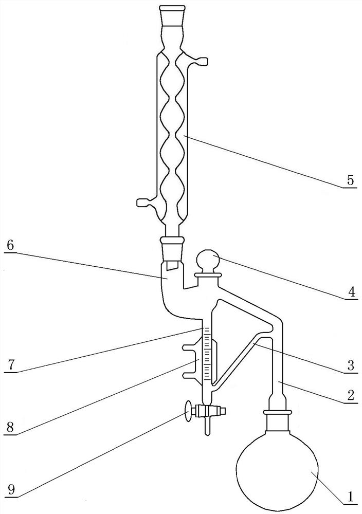
[0016] Embodiment 1: the present invention is the improvement to existing volatile oil extraction device, as figure 1 As shown, this volatile oil extraction separator includes a steam outlet pipe 2 connected to the distillation bottle 1, and the steam outlet pipe 2 is respectively connected with the buffer pipe 6 and the upper nozzle of the overflow pipe 3, and the buffer pipe 6 is connected with the first A condenser 5, the lower part of the buffer tube 6 forms a bent end, and the bottom of the bent end is connected to the top entrance of the measuring tube 7, the inner diameter of the measuring tube 7 is smaller than the inner diameter of the buffering tube 6, and the lower part of the measuring tube 7 The outlet is connected to the lower nozzle of the inclined overflow pipe 3, a valve 9 is installed at the outlet end of the bottom of the measuring pipe 7, and an opening is set at the top of the bending end of the corresponding measuring pipe 7, that is, a volatile oil intake...

Embodiment 2

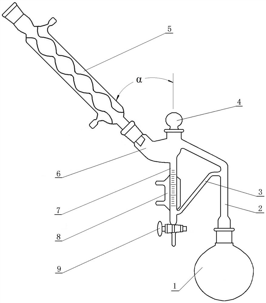
[0017] Embodiment 2: as figure 2 As shown, the difference between this embodiment and Embodiment 1 is that the angle α between the axis of the buffer tube 6 in the vertical section and the axis of the measuring tube 7 is 45°, that is, the orientation of the buffer tube 6 is different from that of Embodiment 1, In Embodiment 1, the interface between the buffer pipe 6 and the first condenser 5 is vertically upward. In this embodiment, since the interface between the buffer pipe 6 and the first condenser 5 faces upward at 45°, the condensation of the first condenser 5 is released. The liquid droplets can slowly flow into the measuring tube 7 along the wall of the inclined buffer tube 6, so as to avoid disturbing the oil surface in the measuring tube 7 and improve the separation effect of volatile oil and water.

[0018] When the present invention is used, the oil-water vapor mixture in the distillation bottle 1 enters the first condenser 5 through the steam outlet pipe 2 and the...


PUM


Abstract

The invention discloses a volatile oil extraction separator which is characterized in that a bent end is formed at the lower part of a buffer tube, the bottom of the bent end is connected with a measuring tube, an opening is formed in the top of the bent end, the opening in the side end part of the bent end is connected with a top port of a steam eduction tube, and a second condenser is arranged at the lower part of the measuring tube. According to the invention, the slide-shaped buffer tube is adopted, so that condensate drops slowly slide downwards along the side tube wall of the buffer tube, in the steam backflow process, the vertical falling speed of the condensate drops is reduced when the condensate drops pass through the buffer tube, the condensate drops horizontally flow into the measuring tube when passing through the bent end at the lower part of the buffer tube, and the vertical speed is very low when the condensate drops slide into the measuring tube; vortex flow generated when the volatile oil is vertically dripped into an oil layer is reduced, the stability of the oil layer is improved, and effective separation of volatile oil and water is achieved. The second condenser is arranged at the lower part of the measuring tube so that higher oil temperature in the upper oil layer can be ensured, the flowability of the oil layer is improved, precipitates in cold water move upwards and are gradually condensed and fused into the upper hot oil layer, and the oil yield of volatile oil can be improved by 10-40%.

Description

technical field [0001] The invention relates to a volatile oil extractor, in particular to a volatile oil extraction separator capable of effectively separating oil and water. Background technique [0002] Volatile oils, also known as essential oils, are mostly colorless or light yellow liquids with a relative density of less than 1. At present, in the classic extractor commonly used to extract volatile oils, during the condensation process, the oil and water vapor form droplets, which drop into the oil surface of the measuring tube in the form of free fall from the end of the condenser, destroying the stability of the oil-water layer interface in the measuring tube At the same time, directly dripping into the oil surface makes the oil-water droplets enter the lower water of the measuring tube due to inertia, causing the separated small oil droplets to suspend in the lower water or adhere to the wall of the measuring tube, resulting in incomplete oil extraction and greatly r...

Claims


Application Information

Patent Timeline
IPC IPC(8): C11B9/02
CPCC11B9/022C11B9/027
Inventor 卜一凡王涛康迪苏国岁赵晖马戎戴亚王蕊何峰刘远上张渝婕
Owner CHINA TOBACCO HEBEI INDUSTRIAL CO LTD
Why Eureka
Try Eureka