Composite slitting roller for transformer cooling fin

A technology for heat sinks and transformers, applied in shearing machine equipment, shearing devices, accessories of shearing machines, etc., can solve the problems of manual manual removal of waste edges, low production efficiency, and waste edge winding equipment.

Pending Publication Date: 2021-08-20
CHANGZHOU ZEMU MACHINERY TECH CO LTD
View PDF0 Cites 0 Cited by
  • Summary
  • Abstract
  • Description
  • Claims
  • Application Information

AI Technical Summary

Problems solved by technology

Due to the irregular movement of the cut waste edge, it is difficult to cut smoothly, often causing the waste edge to entangle the equipment, and the waste edge has to be removed manually, which affects the normal operation of the equipment, and there are hidden dangers in equipment and safety production, high labor intensity and low production efficiency.

Method used


Image

  • Composite slitting roller for transformer cooling fin
  • Composite slitting roller for transformer cooling fin
  • Composite slitting roller for transformer cooling fin

Examples


Embodiment Construction

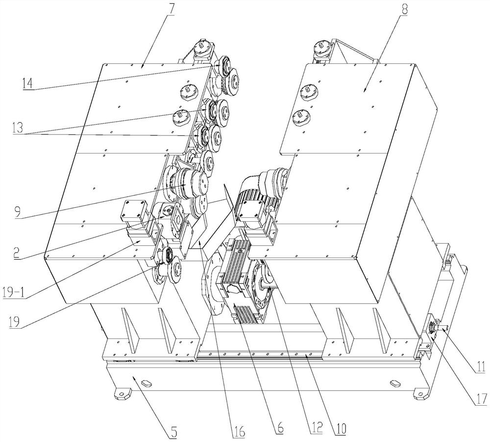
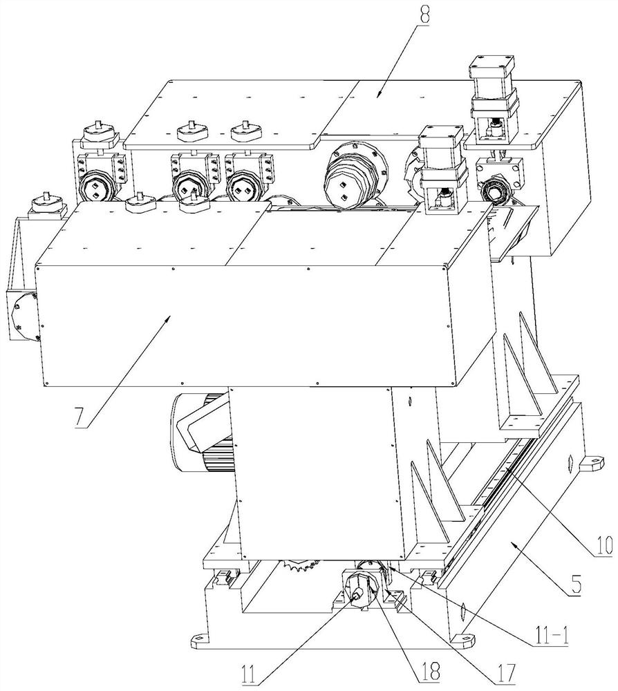
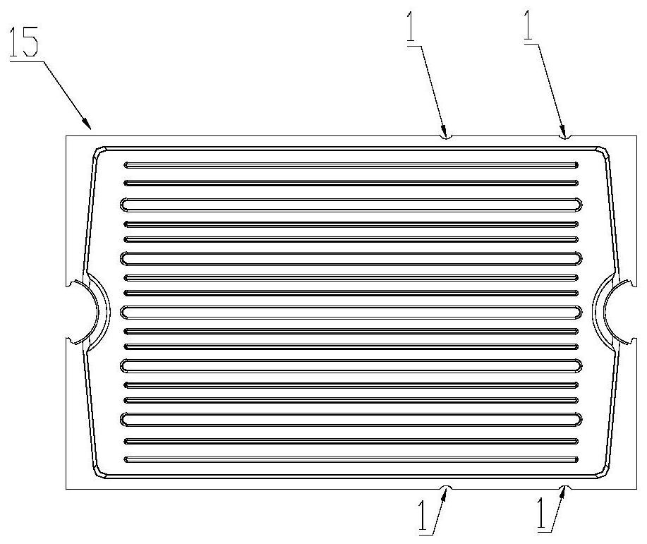
[0027] Such as Figure 1-8 As shown, a compound rolling shear machine for transformer heat sinks includes a frame, a punching mechanism, a rolling shear mechanism and a rolling shear post-processing mechanism. The punching mechanism, the rolling shear mechanism and the rolling shear post-processing mechanism are installed on the On the frame, the transformer cooling fins 15 carry out the punching, rolling shearing and side post-processing after the rolling shearing of the left and right sides of the transformer cooling fins 15 through the punching mechanism, the rolling shearing mechanism and the rolling shearing post-processing mechanism successively. The left and right sides of the transformer cooling fin 15 are punched, and are used to intermittently punch out gaps 1 on the left and right sides of the transformer cooling fin 15 that will be cut off by the rolling before the roll shearing, so that the waste edge components of the rolling cut segment status.

[0028] Such as...


PUM


Abstract

The invention relates to a composite slitting roller for a transformer cooling fin. The composite slitting roller comprises a machine frame, a punching mechanism, a rolling shearing mechanism and a rolling shearing post-processing mechanism, wherein the punching mechanism, the rolling shearing mechanism and the rolling shearing post-processing mechanism are installed on the machine frame from front to back. The transformer cooling fin is subjected to punching, rolling shearing and side post-processing after rolling shearing on the left side and the right side of the transformer cooling fin sequentially through the punching mechanism, the rolling shearing mechanism and the rolling shearing post-processing mechanism, the punching mechanism is used for punching the left side and the right side of the transformer cooling fin, and the punching device is used for intermittently punching gaps on slitter edges, which can be cut off in a rolling mode, on the left side and the right side of the transformer cooling fin before rolling cutting, so that the slitter edges which are cut off in a rolling manner are in a segmented state. The invention has the following beneficial effects: the slitter edges with the punched notch become a segmented state after rolling shearing, so that the slitter edges are not wound on the machine, and the fault of shutdown is avoided.

Description

technical field [0001] The invention relates to a compound rolling shear machine for heat sinks of transformers. Background technique [0002] When the transformer is running, a large amount of heat will be generated due to the lack of eddy current in the transformer core and the load current flowing through the transformer winding. The heat must be dissipated in time, otherwise the transformer will be damaged. The main function of the transformer heat sink is to dissipate the heat generated by the transformer during operation to ensure the normal operation of the transformer. Therefore, the transformer heat sink is an important part of the transformer equipment. [0003] The transformer heat sink is composed of multiple heat sinks, and the heat sink is welded up and down by two layers of heat sinks. The welded heat sink needs to be cut off by rolling shears. [0004] At present, most of the rolling shearing machines used in the transformer heat sink production line on the...

Claims


Application Information

Patent Timeline
Patent Type & Authority Applications(China)
IPC IPC(8): B23D19/04B23D33/02B23D33/00
CPCB23D19/04B23D33/02B23D33/00Y02P70/10
Inventor 张文波柏慧
Owner CHANGZHOU ZEMU MACHINERY TECH CO LTD
Why Eureka
Try Eureka