Pearl perforating equipment for jewelry processing
A pearl and equipment technology, applied in the direction of stone processing equipment, stone processing tools, work accessories, etc., can solve the problems of inability to perform automatic feeding operations, inability to realize automatic drilling, and inconvenience.
- Summary
- Abstract
- Description
- Claims
- Application Information
AI Technical Summary
Problems solved by technology
Method used
Image
Examples
Embodiment 1
[0066] A pearl piercing device for jewelry processing, such as figure 1 As shown, it includes a base 1, a drilling mechanism 2, a feeding mechanism 3 and a clamping and positioning mechanism 4. The upper and rear sides of the base 1 are provided with a drilling mechanism 2, and the upper and front sides of the base 1 are provided with a feeding mechanism 3. The seat 1 is provided with a clamping and positioning mechanism 4 .
[0067]When people want to punch pearls, they can use this pearl piercing equipment for jewelry processing. First, the user places the pearls on the feeding mechanism 3, pushes the feeding mechanism 3 backwards, so that the feeding mechanism 3 is positioned on the drilling mechanism. 2, the pearls are clamped by the clamping positioning mechanism 4, the drilling mechanism 2 is started, and the drilling mechanism 2 punches the pearls. After the pearls are punched, the drilling mechanism 2 is closed, and the Pearl out.
Embodiment 2
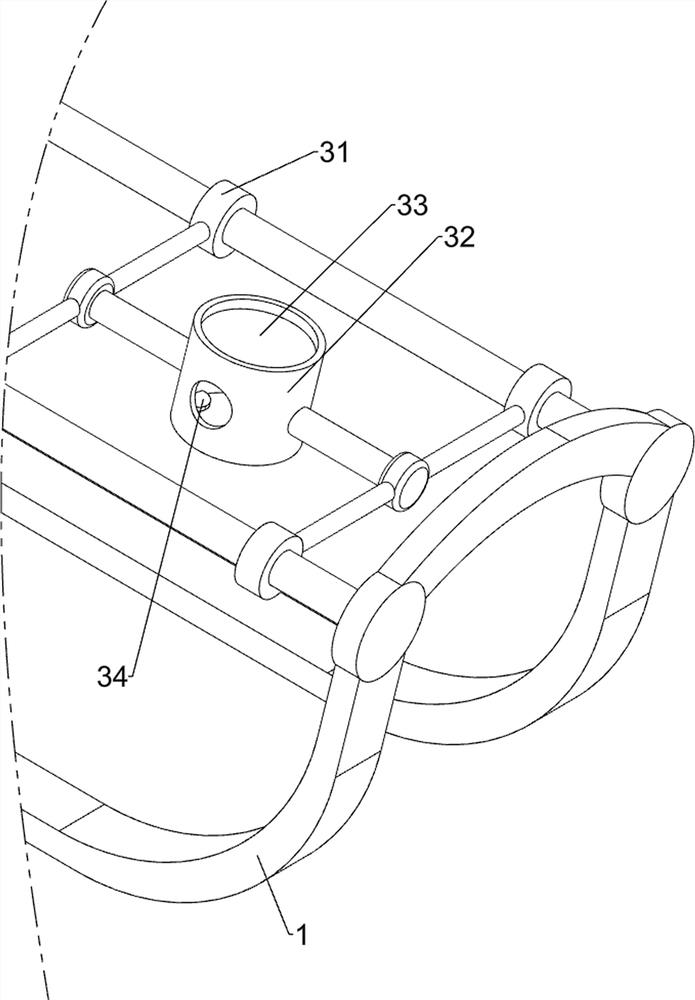
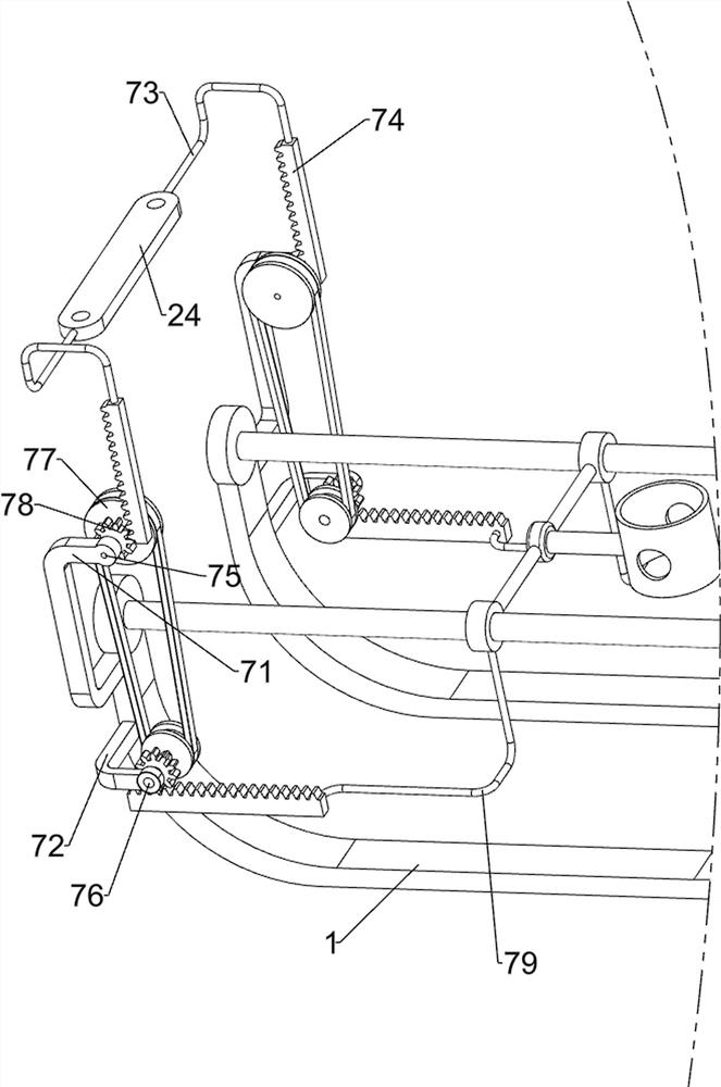
[0069] On the basis of Example 1, such as Figure 2-Figure 4 As shown, the drilling mechanism 2 includes a first support frame 21, a fixed block 22, a spring 23, a slide block 24, a cylinder 25, a second support frame 26, a motor 27 and a drill bit 28, and the rear side of the base 1 is provided with a second A support frame 21, the left and right sides of the first support frame 21 bottom are all provided with fixed blocks 22, the first support frame 21 top sliding type is provided with slide block 24, the first support frame 21 left and right sides are all wound with spring 23, spring 23 two ends are connected with fixed block 22 and slide block 24 respectively, and cylinder 25 is installed on the first support frame 21 tops, and cylinder 25 telescoping rods are connected with slide block 24, and slide block 24 front side is provided with second support frame 26, and the second A motor 27 is installed on the support frame 26, and a drill bit 28 is connected to the output sha...
Embodiment 3
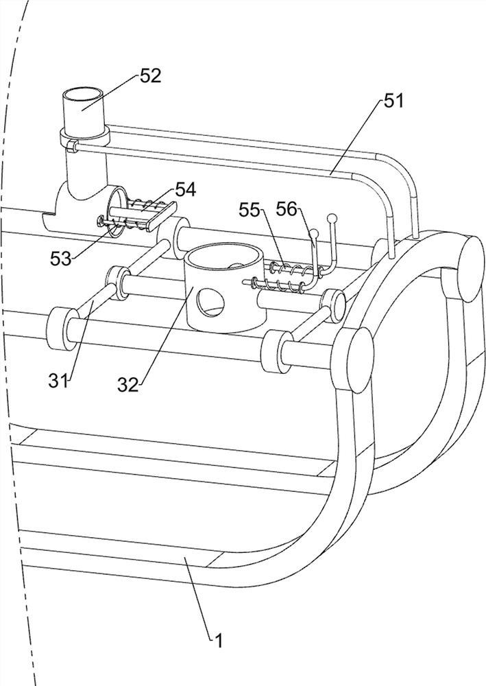
[0076] On the basis of Example 2, such as Figure 5-Figure 7 As shown, a material control mechanism 5 is also included. The upper front side of the base 1 is provided with a material control mechanism 5. The material control mechanism 5 includes a third support frame 51, a feeding tube 52, a second telescopic assembly 53, and a pushing block. 54. The third telescopic assembly 55 and the third special-shaped rod 56, the base 1 is provided with a third support frame 51 on the front side, and the rear side of the third support frame 51 is provided with a feeding tube 52, and the left and right sides of the feeding tube 52 are both A second telescopic assembly 53 is provided, and a pusher block 54 is connected between the two second telescopic assemblies 53, and the pusher block 54 is slidably connected with the feeding pipe 52, and the front side of the storage box 32 is provided with a third telescopic assembly 55, the third special-shaped rods 56 are provided on the two third t...
PUM
 Abstract
Description
Claims
Application Information
 - R&D
- Intellectual Property
- Life Sciences
- Materials
- Tech Scout
- Unparalleled Data Quality
- Higher Quality Content
- 60% Fewer Hallucinations
Browse by: Latest US Patents, China's latest patents, Technical Efficacy Thesaurus, Application Domain, Technology Topic, Popular Technical Reports.
© 2025 PatSnap. All rights reserved.Legal|Privacy policy|Modern Slavery Act Transparency Statement|Sitemap|About US| Contact US: help@patsnap.com


