Device and method for measuring key-phase signal of steam turbine generator unit

A steam turbine generator set and key phase signal technology, which is applied to measuring devices, electrical devices, safety devices, etc., can solve the problems of easily damaged reflective strips, affecting the accuracy of key phase signals, and inability to obtain accurate signals. Complicated steps and required man-hours, realizing the effect of real-time vibration monitoring and continuous and accurate measurement

Pending Publication Date: 2021-08-20
XIAN THERMAL POWER RES INST CO LTD
View PDF8 Cites 0 Cited by
  • Summary
  • Abstract
  • Description
  • Claims
  • Application Information

AI Technical Summary

Problems solved by technology

This method requires that the machine must be shut down before the test, and a maintenance period needs to be specially arranged. Before each test, the reflective strip needs to be re-attached, and the reflective strip is easy to be damaged, stained or peeled off, resulting in the inability to obtain accurate or bonded phase signals.
In addition, if there are oil stains or pits on the surface of the rotor on the same cir

Method used


Image

  • Device and method for measuring key-phase signal of steam turbine generator unit
  • Device and method for measuring key-phase signal of steam turbine generator unit
  • Device and method for measuring key-phase signal of steam turbine generator unit

Examples


Embodiment 1

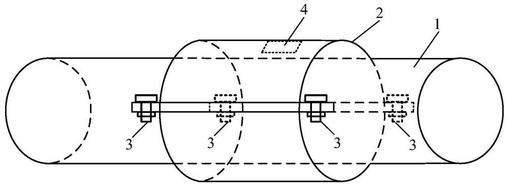
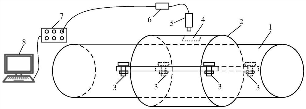
[0029] Example 1: Such as figure 2 As shown, a steam turbine generator set key signal measuring device and a measurement method comprising a slotting hoop 2, a TV turntable phase sensor 5, a fronter 6, and a data acquisition device 7. First installed on the rotor 1 figure 1 The slotted hoop 2 is shown, the slotting hoop 2 is opened with a measuring groove 4, and the eddy current key sensor 5 is positively pair of measuring grooves 4, and is fixed to the sensor holder, and then the eddy current key phase sensor 5 is The front member 6 is connected, and the output of the fronter 6 is connected to the data acquisition device 7, and the data acquisition device is connected to the computer 8. When the turbine generator sets, the rotor 1 rotates at high speed, and whenever the measuring groove 4 passes the eddy current key sensor 5, it will produce Figure 4 The pulse signal shown, that is, a key signal. The device can realize the long-term and stable measurement of the key signal of the...

Embodiment 2

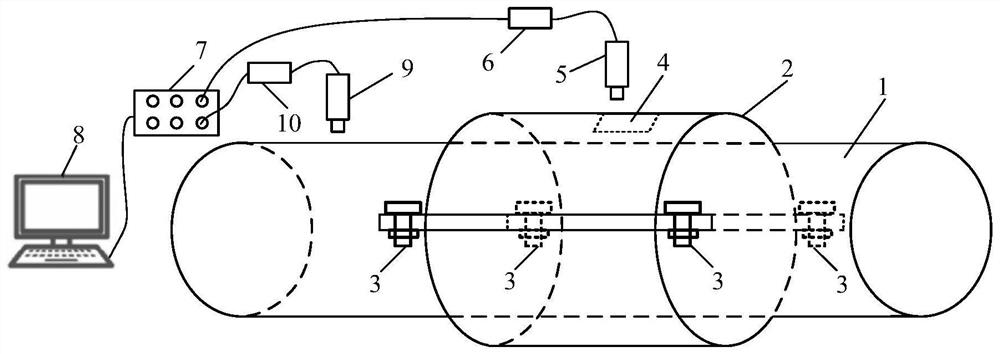
[0033] Example 2: Such as image 3 As shown, a steam turbine generator set key signal and a vibration phase measuring device and a measurement method include a slotting hoop 2, a vortex stream key sensor 5, a vortex stream key sensor front, a vibration sensor 9, vibration Sensor front device 10, and data acquisition device 7. First installed on the rotor 1 figure 1 The slotted hoop 2 is shown, the slotting hugging surface is opened with a measuring groove 4, and the vortex stream key sensor 5 is positively to the measuring groove 4, and is fixed to the sensor holder, and then the eddy current key sensor 5 and the front The device 6 is connected. The vibration sensor 10 is mounted in the radial direction of the rotor 1 and is fixed to the sensor holder, and then the vibration sensor 9 is connected to the fronter 10. Connect the output of the front member 6 and the fronter 10 to the data acquisition device 7, the data acquisition device is connected to the computer 8. The number of d...


PUM

PropertyMeasurementUnit
The peakaaaaaaaaaa
Depthaaaaaaaaaa
Widthaaaaaaaaaa

Abstract

The invention relates to a device and method for measuring a key-phase signal of a steam turbine generator unit. The device comprises a rotor, wherein the rotor is provided with a slotted hoop, the surface of the slotted hoop is provided with a measuring groove, the measuring groove is provided with an eddy current key phase sensor in an opposite manner, the eddy current key phase sensor is fixed on a sensor support, the eddy current key phase sensor is connected with the input end of a preposition device, the output end of the preposition device is connected with one end of a data acquisition device, and the other end of the data acquisition device is connected with a computer. The device and method capable of continuously and stably measuring the key-phase signal in a long-term manner is provided for the steam turbine generator unit without the key-phase signal, and the vibration phase can be accurately obtained by combining a vibration sensor.

Description

Technical field [0001] The present invention relates to the field of vibration signal measurement, and in particular, there is a method of measurement means and measurement method for steam wheel generator set bond signal. Background technique [0002] Vibration accounts for a significant proportion in the failure of steam wheel generator, which is an important factor affecting equipment safety, stability and economic operation. Vibration is an important indicator of the safety assessment of the steam turbine generator, which directly reflects the health of the steam turbine generator set. The vibration phase is a key parameter that handles the vibration failure caused by quality imbalance, and the key to accurately obtaining the vibration phase is to obtain the key signal. [0003] Typically, large steam turbine generator sets have the corresponding key-phase sensors at the head or machine tail for key phase signal measurement. However, many small turbine generators (especially ...

Claims


Application Information

Patent Timeline
IPC IPC(8): F01D21/00F01D21/14G01H11/06
CPCF01D21/003F01D21/14G01H11/06
Inventor 胡启龙张恒张卫军陈旭东卫大为赵博董雷韩传高马晓珑
Owner XIAN THERMAL POWER RES INST CO LTD
Why Eureka
Try Eureka