
Luneberg lens antenna

A Lumber lens antenna and resonant unit technology, applied to antennas, electrical components, etc., can solve the problems of lower production cost, low production difficulty, and phase shift

Pending Publication Date: 2021-08-20
无锡威尔利斯技术有限公司
View PDF0 Cites 0 Cited by
  • Summary
  • Abstract
  • Description
  • Claims
  • Application Information

AI Technical Summary

Problems solved by technology

[0003] The purpose of the present invention is to provide a Luneberg lens antenna for microwave frequency bands, which can solve the phase shift problem caused by the direction of incident waves
[0005] Four metal split resonant rings are used to form a resonant unit with a square-shaped structure. The four directions of the square are respectively provided with openings, which can receive electromagnetic waves from all directions. It is insensitive and can be applied to linear polarization incidence and circular polarization incidence; in addition, the resonant unit of this application has a simple structure and low manufacturing difficulty, which is conducive to reducing manufacturing costs

Method used


Image

  • Luneberg lens antenna
  • Luneberg lens antenna
  • Luneberg lens antenna

Examples


Embodiment

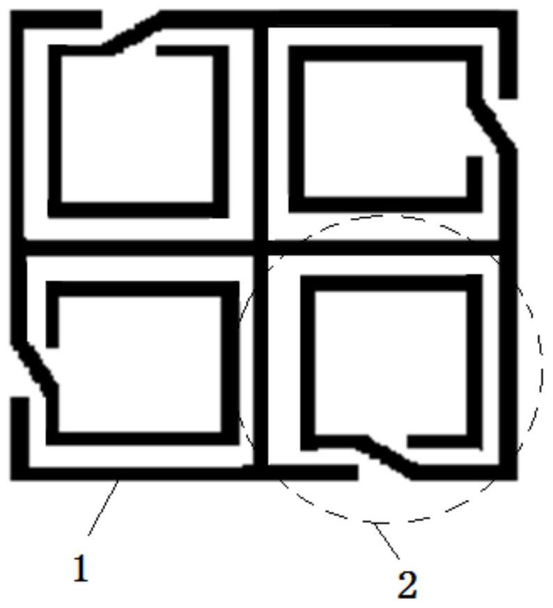
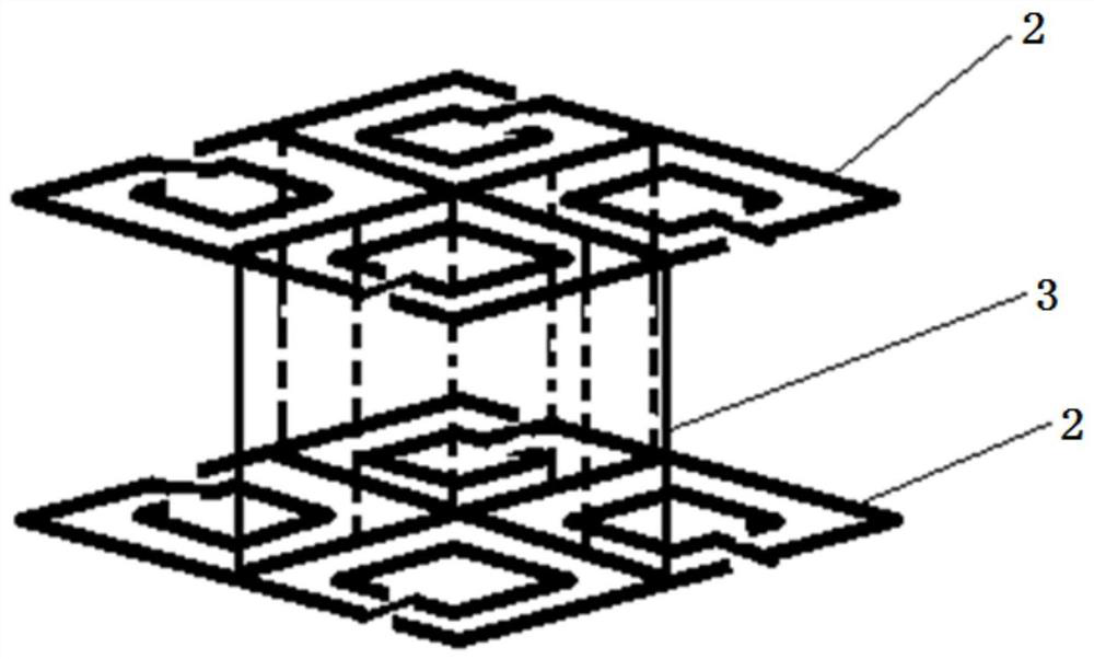
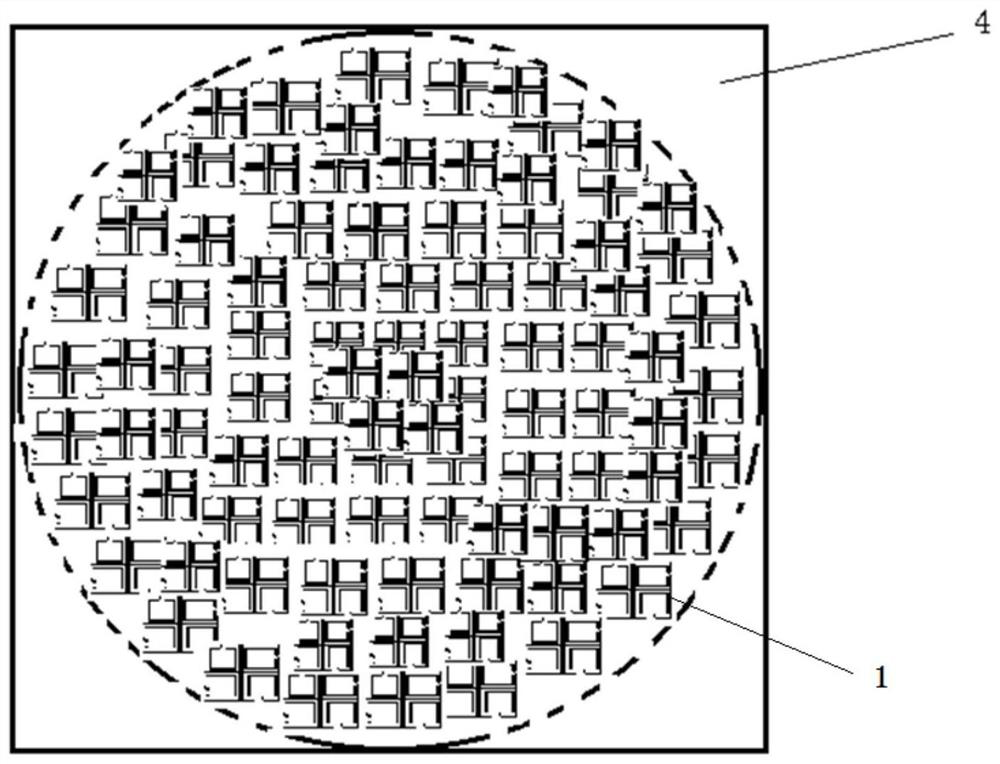
[0024] Embodiment: the application provides a Lunberg lens antenna, such as figure 1 As shown, the Lunberg lens antenna includes: at least one resonant unit 1, and each resonant unit 1 includes four metal split resonators 2 forming a grid-shaped structure; the plane of the resonant unit 1 is square as a whole, and each metal split resonator 2 The openings are respectively located in the four directions of the square.

[0025] figure 1 Among them, the equivalent circuit of a metal split resonant ring 2 is similar to an LC filter circuit composed of capacitors and inductors. Four such metal split resonant rings 2 are designed as a whole, which is a square as a whole, roughly in the shape of "Tian", up, down, left, and right An opening is provided respectively.

[0026] By setting openings in the four directions of the resonant unit 1 with a square-shaped structure, electromagnetic waves in all directions can be received, and the problem of distortion of the refracted wave dire...


PUM


Abstract

The invention discloses a Luneberg lens antenna. The antenna comprises at least one resonance unit, and each resonance unit comprises four metal opening resonance rings forming a structure shaped like a Chinese character 'tian'. The whole plane of the resonance unit is square, and the openings of the metal opening resonance rings are located in the four directions of the square respectively. The four metal opening resonance rings form the resonance unit of the structure shaped like the Chinese character 'tian', openings are formed in the four directions of the square, electromagnetic waves in all directions can be received, the incident wave direction problem caused by the single opening direction is solved, the antenna is not sensitive to the incident wave polarization direction, and the antenna can be suitable for linear polarization incidence and circular polarization incidence; in addition, the resonance unit is simple in structure and low in manufacturing difficulty, and the manufacturing cost can be reduced.

Description

technical field [0001] The invention belongs to the field of Lunberg lenses, and relates to a Lunberg lens antenna. Background technique [0002] The Luneberg lens antenna is a spherically symmetrical dielectric lens antenna with a dielectric constant that gradually changes from 1 to 2. The spherical focal plane at a certain distance from the lens surface can be considered as its focus. By placing several feed antennas on the surface of the lens, the multi-beam performance can be easily obtained. The spherical electromagnetic wave emitted by the feed source at the focal point can be transformed into a plane electromagnetic wave by the refraction of the Lunberg lens. Due to this characteristic of the Lunberg lens , which can be applied to the design of high-gain antennas. At present, Lunberg lens antennas have been widely used. Lumber lens antennas are usually manufactured in the shape of a hemisphere instead of a complete sphere. The bottom surface of the hemisphere is made...

Claims


Application Information

Patent Timeline
IPC IPC(8): H01Q15/08
CPCH01Q15/08Y02D30/70
Inventor 赵鲁豫刘洋赵筱元龙今朝
Owner 无锡威尔利斯技术有限公司
Learn More