

Sound signal processing method and sound signal processing device
A signal processing device and signal processing technology, applied in signal processing, speech analysis, public address system, etc., can solve the problem of inability to realize sound field assistance
- Summary
- Abstract
- Description
- Claims
- Application Information
AI Technical Summary
Problems solved by technology
Method used
Image

Examples
Embodiment approach 1
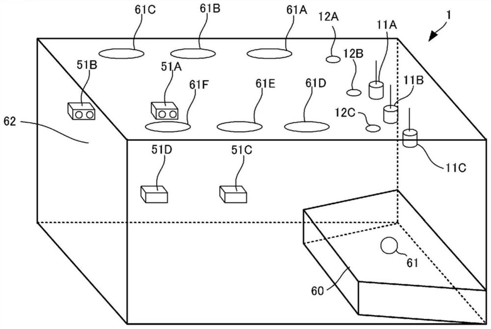
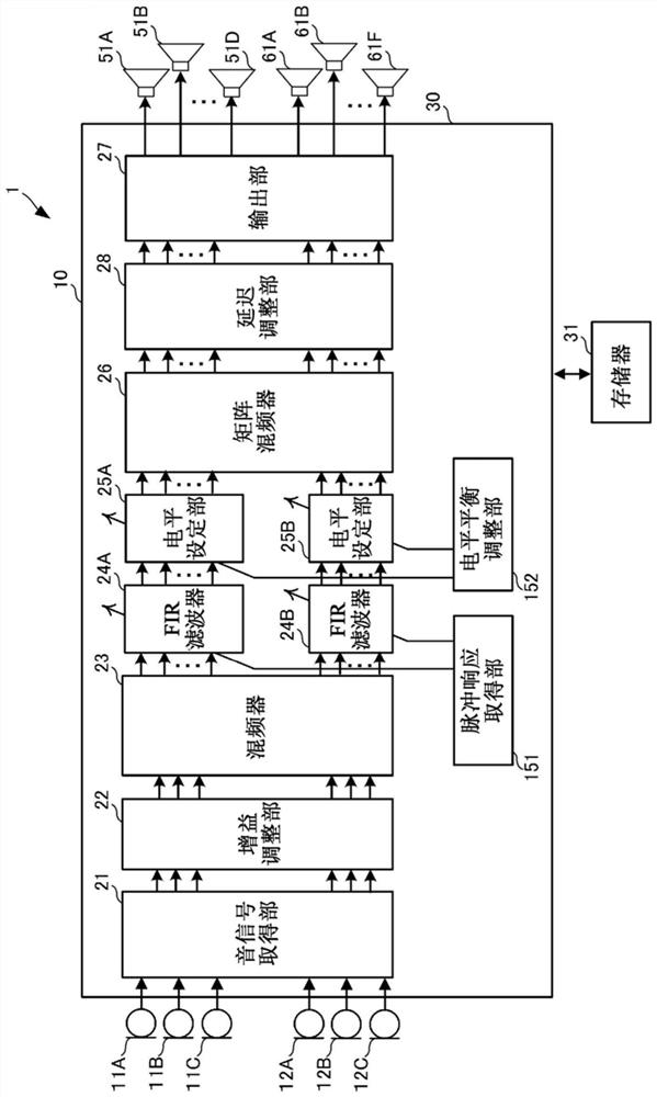
[0031] figure 1 It is a perspective perspective view schematically showing the chamber 62 constituting the space. figure 2 It is a block diagram showing the configuration of the sound field assisting system 1 .
[0032] The chamber 62 constitutes a substantially rectangular parallelepiped space. A sound source 61 exists on a stage 60 in front of a room 62 . The rear of the room 62 corresponds to an auditorium where the audience sits. In addition, the shape of the chamber 62 and the arrangement of sound sources are not limited to figure 1 example of. The sound signal processing method and sound signal processing device of the present invention can provide a desired sound field regardless of the shape of the space, and can realize richer sound and image and space expansion than before.
[0033] The sound field assisting system 1 has a directional microphone 11A, a directional microphone 11B, a directional microphone 11C, an omnidirectional microphone 12A, an omnidirectiona...
Embodiment approach 2
[0095] refer to Figure 8 , Figure 9 , Figure 10 and Figure 11 A sound field assisting system 1A according to Embodiment 2 will be described. Figure 8 It is a perspective perspective view schematically showing the space 620 . Figure 9 It is a plan view overlooking the observation space 620 . Figure 10 It is a block diagram showing the configuration of the sound field assisting system 1A.
[0096] Figure 11 is a flowchart showing the operation of the audio signal processing device. In this example, it is assumed that the sound source 61 moves on the stage 60 or that a plurality of sound sources 61 exist on the stage 60 . In addition, about the same structure as Embodiment 1 mentioned above, the same code|symbol is attached|subjected, and description is abbreviate|omitted.
[0097] Sound field auxiliary system 1A such as Figure 8 and Figure 9 As shown, there are speaker 52A, speaker 52B, speaker 52C, speaker 52D, speaker 52E, speaker 53A, speaker 53B, speaker ...
Embodiment approach 3
[0143] refer to Figure 13 , Figure 14 and Figure 15 A sound field assisting system 1B according to Embodiment 3 will be described. Figure 13 It is a perspective perspective view schematically showing the chamber 62B of the third embodiment. Figure 14 It is a block diagram showing the configuration of the sound field assisting system 1B. Figure 15 is a flowchart showing the operation of the audio signal processing device according to the third embodiment. Embodiment 3 assumes a case where output sounds from the sound source 611B, the sound source 612B, and the sound source 613B are line-input. In addition, about the same structure as Embodiment 1 mentioned above, the same code|symbol is attached|subjected, and description is abbreviate|omitted. Line input refers to inputting sound signals from audio cables connected to the sound source instead of picking up sound output from sound sources such as various musical instruments described later with a microphone. On the ...
PUM
 Abstract
Description
Claims
Application Information