Air inlet plate with structure improved and for air channel of cotton-spinning combing machine

A structure improvement and combing machine technology, which is applied in the direction of combing machines, textiles and papermaking, fiber processing, etc., can solve the problems of increased head box temperature rise, difficult air flow compensation, and inability to clean the bottom side of the head box, etc., to achieve Cleaning aid reduces and improves air distribution

Active Publication Date: 2013-10-30
JIANGSU KAIGONG MACHINERY
View PDF4 Cites 0 Cited by
  • Summary
  • Abstract
  • Description
  • Claims
  • Application Information

AI Technical Summary

Problems solved by technology

As the speed of the combing machine continues to increase, the influence of the air flow in the air duct on the quality of the cotton web continues to increase, and the temperature rise of the head box also increases; under this background, the simple blocking mechanism of the original air inlet plate is difficult to effectively To the effect of air duct airflow compensation, and to isolate the air duct from the head box, it is impossible to clean the bottom side of the head box and reduce the temperature of the head box

Method used


Image

  • Air inlet plate with structure improved and for air channel of cotton-spinning combing machine
  • Air inlet plate with structure improved and for air channel of cotton-spinning combing machine

Examples


Embodiment

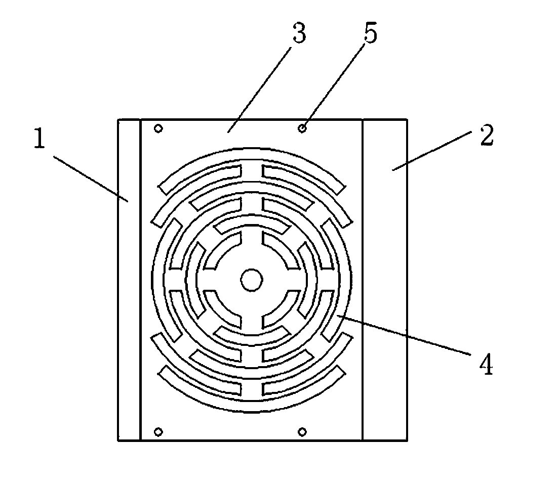
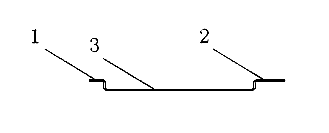
[0013] Embodiment: A structure-improved air inlet plate for the air duct of a cotton spinning comber, which is fixed on the flange on the head side flange of the air duct of the comber, and the air inlet plate includes left and right air suction plates 1, 2 and a central The air supply plate 3, the left and right air suction plates 1 and 2 are fixed on both sides of the central air supply plate 3, and the left and right air suction plates 1 and 2 are formed through the flange side wall of the comber air duct head side respectively The left and right air suction passages of the central air supply plate 3 are provided with a supplementary air hole 4, and the two axial sides of the supplementary air hole 4 are connected with the air duct and the bottom side of the head box respectively, and the two ends of the supplementary air hole 4 are respectively connected with the The air duct is corresponding to the rear side of the main motor, so that the supplementary air hole 4 connects ...


PUM


Abstract

The invention discloses an air inlet plate with the structure improved and for an air channel of a cotton-spinning combing machine. The air inlet plate is fixed on a flange on the head side of the air channel of the combing machine. The air inlet plate comprises a left air suction plate, a right air suction plate and a central air compensation plate, wherein the left and right air suction plates are fixedly positioned on two sides of the central air compensation plate, the left and right air suction plates and the side wall of the flange on the head side of the air channel of the combing machine form left and right air suction channels which are communicated with each other, an air compensation hole is formed in the central compensation plate, and two axial sides of the air compensation hole are corresponding communicated with the air channel and the bottom side of a head box respectively. According to the air inlet plate with the structure improved, the left and right air suction channels and the central air compensation hole are formed in the air inlet plate fixed on the flange on the head side of the air channel of the combing machine, airflow compensation is formed on the end face of the air channel of the combing machine, and improving of airflow distribution among combing eyes is facilitated; directional flow of airflow is formed under the drive the negative pressure of the air channel, meanwhile, the bottom side of the head box can be cleaned, and the air inlet plate can assist in reducing the temperature of the head box.

Description

technical field [0001] The invention relates to an air inlet plate of an air duct of a cotton spinning combing machine, in particular to an air flow distribution of an air duct of a cotton spinning combing machine. Background technique [0002] The combing machine is a spinning equipment used to remove short fibers, neps, and impurities in the combed small laps to form a combed sliver with a certain degree of parallelism, straightness, and separation. As the speed of the combing machine continues to increase, the influence of the air flow in the air duct on the quality of the cotton web continues to increase, and the temperature rise of the head box also intensifies; under this background, the simple blocking mechanism of the original air inlet plate is difficult to effectively To the air duct airflow compensation, and to isolate the air duct and the head box, it is impossible to clean the bottom side of the head box and reduce the temperature of the head box. Contents of ...

Claims


Application Information

Patent Timeline
Patent Type & Authority Applications(China)
IPC IPC(8): D01G19/28
Inventor 张立彬
Owner JIANGSU KAIGONG MACHINERY
Why Eureka
Try Eureka