Handheld ring for probe protective sleeve, disposable probe protective sleeve assembly and assembling method
A protective cover and hand-held ring technology, applied in applications, infrasound diagnosis, ultrasonic/sonic/infrasonic diagnosis, etc., can solve problems such as inability to effectively avoid cross-infection, and achieve the effect of avoiding repeated work, improving comfort, and convenient operation.
- Summary
- Abstract
- Description
- Claims
- Application Information
AI Technical Summary
Problems solved by technology
Method used
Image

Examples
Embodiment 1
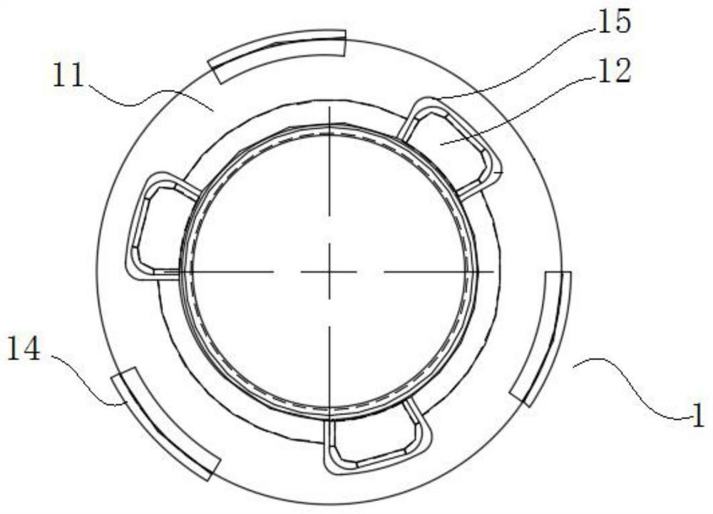
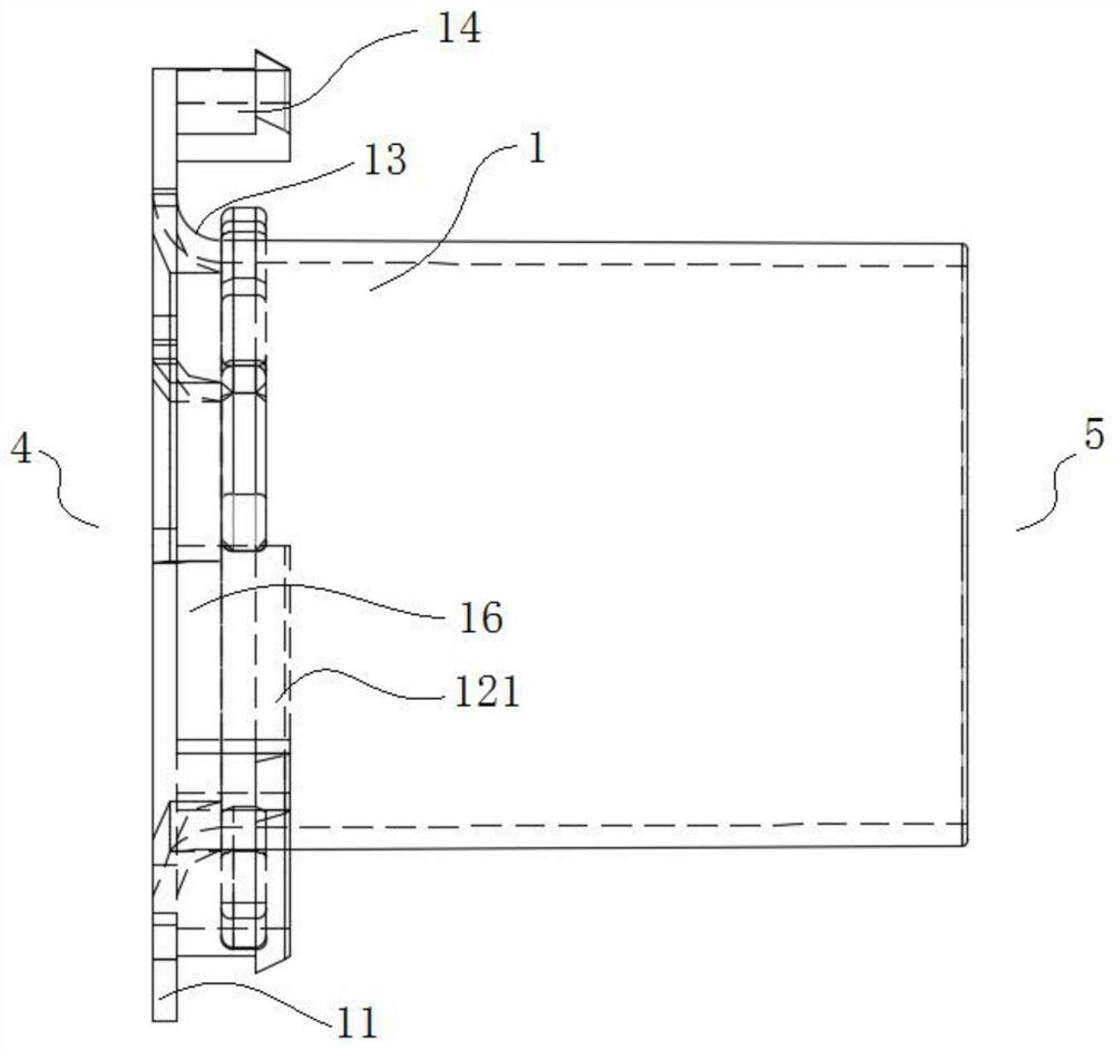
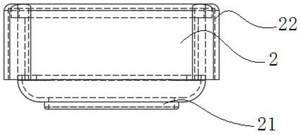
[0051] Such as Figure 1-5As shown, this embodiment provides a hand-held ring for a probe protective sleeve, which includes a cylinder body 1 and an end cap 2, wherein the probe protection sleeve 3 can be sleeved on the outside of the cylinder body 1; the head end 4 and the end 5 of the cylinder body 1 are both The opening is set, and the edge of the head end of the cylinder 1 is bent outward along the radial direction of the cylinder 1 to form a flange 11. The axial section of the cylinder 1 is similar to a "several" shape, and the head of the cylinder 1 is provided with a fixed The rib ring fixing member 12 of the rib ring 35 of the probe protective cover 3; the end cap 2 is a cylindrical end cap with openings on the head end 4 and the end 5, and the cylindrical end cap is sleeved outside the cylinder body 1, and the cylindrical end cap The head end 4 is docked with the flange 11, and an annular cavity (not shown) for accommodating the probe protective cover 3 is formed betw...
PUM
 Abstract
Description
Claims
Application Information
 - R&D
- Intellectual Property
- Life Sciences
- Materials
- Tech Scout
- Unparalleled Data Quality
- Higher Quality Content
- 60% Fewer Hallucinations
Browse by: Latest US Patents, China's latest patents, Technical Efficacy Thesaurus, Application Domain, Technology Topic, Popular Technical Reports.
© 2025 PatSnap. All rights reserved.Legal|Privacy policy|Modern Slavery Act Transparency Statement|Sitemap|About US| Contact US: help@patsnap.com