
a motor

A motor housing and mounting plate technology, applied in the direction of electromechanical devices, electrical components, electric components, etc., can solve the problems of not being able to clean up grains in time, motor performance degradation, and buried motors

Active Publication Date: 2022-07-12
江苏锡安达防爆股份有限公司
View PDF16 Cites 0 Cited by
  • Summary
  • Abstract
  • Description
  • Claims
  • Application Information

AI Technical Summary

Problems solved by technology

[0004] The purpose of the present invention is to solve the problem that in the traditional small civil grain thresher, because the farmers are busy putting the grain in the threshing mechanism, they cannot clean up the grain grains falling below the thresher mechanism in time, resulting in excessive accumulation of grain grains and burying the motor. Effective heat dissipation is not obtained, which reduces the performance of the motor. A motor is proposed

Method used


Image

  • a motor
  • a motor
  • a motor

Examples


Embodiment Construction

[0018] The technical solutions in the embodiments of the present invention will be clearly and completely described below with reference to the accompanying drawings in the embodiments of the present invention. Obviously, the described embodiments are only a part of the embodiments of the present invention, rather than all the embodiments. Based on the embodiments of the present invention, all other embodiments obtained by those of ordinary skill in the art without creative efforts shall fall within the protection scope of the present invention.

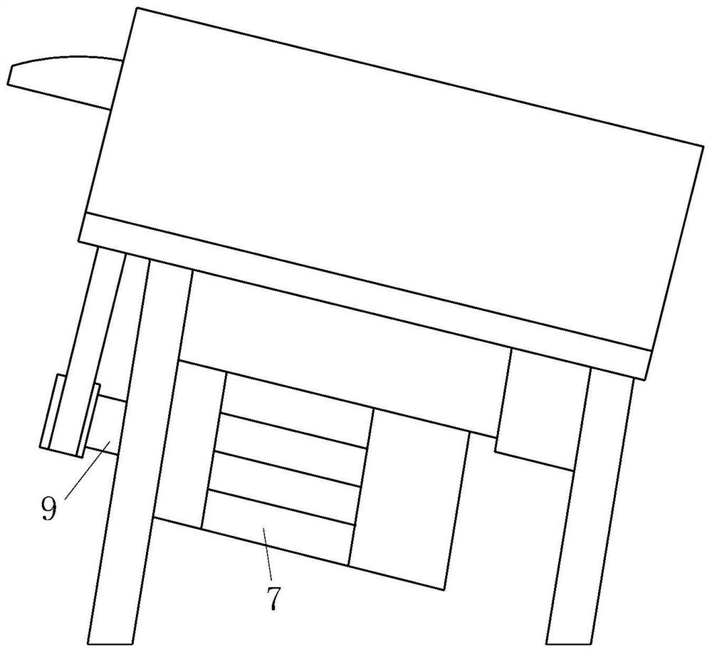
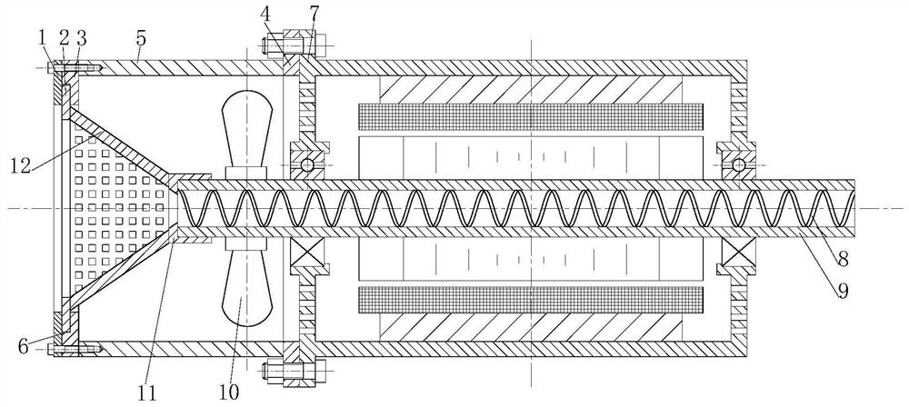
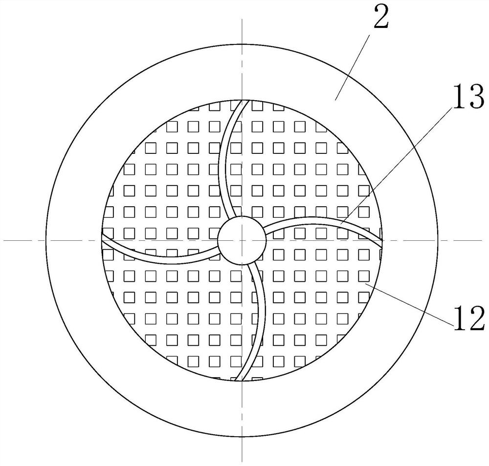
[0019] Please refer to Figure 1-3 , the present invention provides a technical solution: a motor, including a motor housing 7, the left side of the motor housing 7 is fixedly connected with a dust cover, the dust cover includes a mounting plate 4, the installation The plate 4 is fixedly connected with the motor housing 7 through bolts, and the side of the mounting plate 4 away from the motor housing 7 is fixedly connected with a mou...


PUM


Abstract

The present invention relates to the technical field of motors, and in particular, to a motor. It includes a motor housing, the left side of the motor housing is fixedly connected with a dust cover, the dust cover includes a first mounting plate, and the first mounting plate is fixedly connected with the motor housing through bolts, so The side of the first mounting plate away from the motor housing is fixedly connected with a mounting cylinder, the left side of the mounting cylinder is fixedly connected with a clamping plate, and a groove on the clamping plate is slidably connected with an annular sliding plate, and the annular sliding plate is slidably connected. An annular baffle is arranged on the left side of the annular slide plate, a conical filter screen is fixedly connected to the right side of the annular slide plate, a clamping block is fixedly connected to the right side of the conical filter screen, and a rotating shaft is fixed in the clamping groove of the clamping block. , Fan blades are installed on the rotating shaft, the fan blades cool the motor, the conical filter brings the grains into one end of the rotating shaft, and the spiral body inside the rotating shaft brings the grains to the other end of the rotating shaft.

Description

technical field [0001] The present invention relates to the technical field of motors, and in particular, to a motor. Background technique [0002] The motor uses the coil energization to generate a rotating magnetic field and acts on the rotor to form a magneto-electric power rotating torque to make the motor rotate. [0003] For traditional small civilian grain threshers, farmers need to put the threshed grains into the threshing mechanism located above the motor, and the grains fall below the thresher mechanism. Because farmers are busy putting grains in the threshing mechanism, they cannot clean up the grains in time. As a result, the motor is buried due to the accumulation of too many grains, so that the motor cannot be effectively dissipated, and the performance of the motor is reduced. Therefore, a motor is proposed. SUMMARY OF THE INVENTION [0004] The purpose of the present invention is to solve the problem that in the traditional small-scale civilian grain thre...

Claims


Application Information

Patent Timeline
Patent Type & Authority Patents(China)
IPC IPC(8): H02K5/10H02K9/06H02K5/20
CPCH02K5/10H02K9/06H02K5/20
Inventor 张涵宇华彬
Owner 江苏锡安达防爆股份有限公司
Learn More