A kind of pavement marking equipment for construction engineering

A technology for scribing equipment and construction engineering, which is applied in the directions of buildings, roads, roads, etc., can solve the problems of uneven moving speed of scribing equipment, accumulation or leakage of paint at the scribing part, time-consuming and labor-intensive, etc. Small, uniform speed, simple operation effect

Active Publication Date: 2022-07-22
江西华翔建筑有限责任公司
View PDF18 Cites 0 Cited by
  • Summary
  • Abstract
  • Description
  • Claims
  • Application Information

AI Technical Summary

Problems solved by technology

[0004] In order to overcome the disadvantages that the existing road marking equipment is cumbersome to operate, time-consuming and labor-intensive, and the speed of manually pushing the marking equipment is not uniform, which will lead to the phenomenon of paint accumulation or leakage in the marking part, the technical problem to be solved is : To provide a road marking device for construction engineering that is easy to operate and does not have the phenomenon of paint accumulation or missing coating

Method used


Image

  • A kind of pavement marking equipment for construction engineering
  • A kind of pavement marking equipment for construction engineering
  • A kind of pavement marking equipment for construction engineering

Examples


Embodiment 1

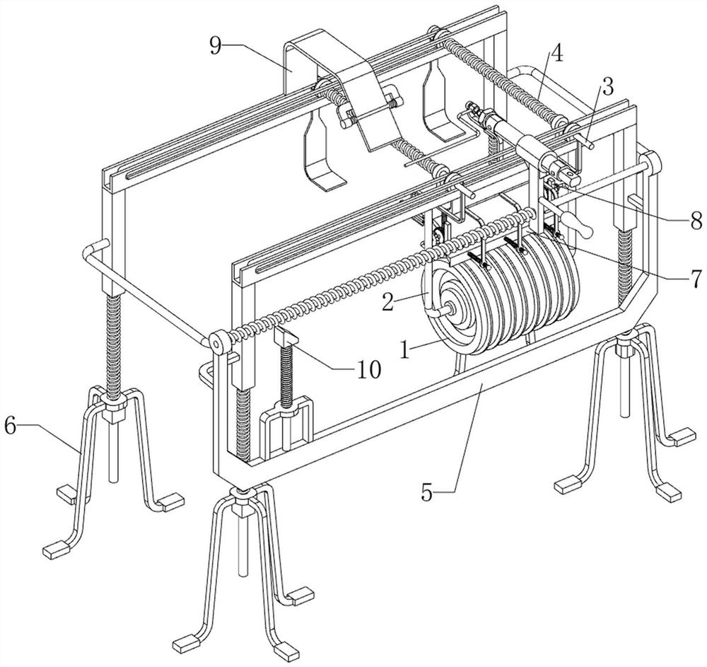
[0060] A kind of pavement marking equipment for construction engineering, such as figure 1 and figure 2 As shown, it includes a wire wheel 1, a connecting rod 2, a guide rod 3, a first spring 4, a moving mechanism 5 and an ascending mechanism 6. The ascending mechanism 6 is provided with a moving mechanism 5, and the ascending mechanism 6 is slidably provided with two guides. Rod 3, a connecting rod 2 is slidably provided between the front sides of the guide rod 3, the lower part of the connecting rod 2 is rotatably provided with a wire wheel 1, and a first spring 4 is provided between the upper rear side of the connecting rod 2 and the two guide rods 3 .

[0061] The lifting mechanism 6 includes a support foot 60, a connecting block 61, a second spring 62 and a slide rail 63. The top of the four support feet 60 is slidably provided with a connecting block 61 in the middle. The upper part of the connecting block 61 is connected to the top of the support foot 60 on the same s...

Embodiment 2

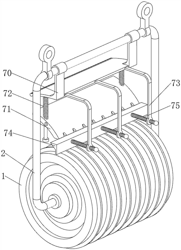
[0065] On the basis of Example 1, as figure 1 , image 3 , Figure 4 and Figure 5 As shown, it also includes a cleaning mechanism 7. The cleaning mechanism 7 includes a fixing plate 70, a cleaning plate 71, a third spring 72, a guide plate 73, a stopper 74 and a fourth spring 75. The upper part of the connecting rod 2 is provided with a fixing plate 70. The lower part of the fixing plate 70 is slidably provided with a cleaning plate 71. The cleaning plate 71 cooperates with the wire wheel 1. A third spring 72 is provided between the left and right sides of the top of the cleaning plate 71 and the fixing plate 70. The upper part of the front side of the fixing plate 70 is spaced apart. Three guide plates 73 are provided, and a block 74 is slidably provided between the lower parts of the guide plates 73 .

[0066] It also includes a reset mechanism 8. The reset mechanism 8 includes a top plate 80, a ratchet tooth 81, a rotating shaft 82, a ratchet wheel 83, a gear 84 and a r...

Embodiment 3

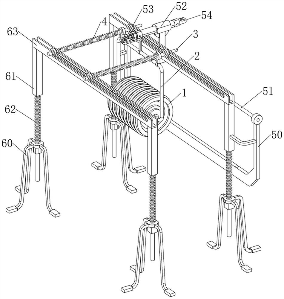
[0069] On the basis of Example 2, as figure 1 , Image 6 and Figure 7 As shown, a trigger mechanism 9 is also included. The trigger mechanism 9 includes a mounting plate 90, a turning plate 91, a torsion spring 92 and a fixing rod 93. A mounting plate 90 is provided in the middle of the top of the slide rail 63 on the rear side. The front side of the mounting plate 90 The lower part is rotatably provided with a turning plate 91, the left and right sides of the turning plate 91 and the mounting plate 90 are provided with torsion springs 92, the rear side of the telescopic rod of the cylinder 54 is provided with a fixing rod 93, and the fixing rod 93 cooperates with the turning plate 91, The fixing rod 93 is located on the front side of the connecting plate 53 .

[0070] When people control the extension of the telescopic rod of the air cylinder 54, the connecting plate 53, the connecting rod 2, the wire wheel 1 and the fixing rod 93 are driven to move backward, thereby compl...


PUM


Abstract

The invention relates to a scribing device, in particular to a pavement scribing device for construction engineering. The technical problem to be solved is: to provide a pavement marking device for construction engineering which is easy to operate and does not cause paint accumulation or paint leakage. The invention provides such a pavement marking device for construction engineering, which includes a moving mechanism and a lifting mechanism, and the lifting mechanism is provided with a moving mechanism; a guide rod, two guide rods are slidably arranged on the lifting mechanism; a connecting rod, a guide rod A connecting rod is slidably arranged between one side of the rod; a wire wheel, the lower part of the connecting rod is rotatably provided with a wire wheel; a first spring, a first spring is provided between the upper side of the connecting rod and the two guide rods. Through the cooperation of the wire wheel, the moving mechanism and the lifting mechanism, the invention can automatically complete the marking operation on the road surface, has a small footprint, simple operation, and the speed of the wire wheel moving is uniform, and the phenomenon of paint leakage and accumulation will not occur. .

Description

technical field [0001] The invention relates to a marking device, in particular to a road marking device for construction engineering. Background technique [0002] Road traffic markings are traffic safety facilities composed of various lines, arrows, characters, raised road signs, etc. marked on the road surface. The function of road traffic markings is to transmit standardized information and to control and guide traffic. [0003] The existing road marking equipment needs to manually open the discharge port manually when marking, and then push the marking equipment to move for marking. As a result, the scribing is stopped, the operation is more troublesome, time-consuming and laborious, and when the scribing equipment is moved manually, if the speed is not uniform, it will lead to the phenomenon of paint accumulation or leakage at the scribing part, and the lines are more ugly. Pavement marking equipment for construction projects that is easy to operate and does not exper...

Claims


Application Information

Patent Timeline
Patent Type & Authority Patents(China)
IPC IPC(8): E01C23/20
CPCE01C23/203
Inventor 赵超臣洪兆晶何龙胜
Owner 江西华翔建筑有限责任公司
Why Eureka
Try Eureka