Accurate positioning device for high-turnover frame column main reinforcements

A technology of precise positioning and frame columns, which is applied in the direction of buildings, building reinforcements, building components, etc., can solve the problems of difficult precise positioning, poor turnover performance, time delay, etc., and achieve improved positioning range, small quality deviation, and convenient operation Effect

Pending Publication Date: 2021-08-27
CHINA CONSTR FIFTH ENG DIV CORP LTD
View PDF0 Cites 0 Cited by
  • Summary
  • Abstract
  • Description
  • Claims
  • Application Information

AI Technical Summary

Problems solved by technology

When the main reinforcement is installed upward on the frame column, the position of the main reinforcement is easy to shift as the installation height increases
After pouring the beams, slabs, walls, and columns of this layer, the position of the main reinforcement on the upper floor often exceeds the deviation allowed by the code, and the main reinforcement must be repositioned. The adjustment is time-consuming and laborious, and the effect is not ideal. It is easy to cause quality defects such as exposed reinforcement of the frame column , which increases the cost and affects the quality and safety of the project
[0003] The traditional method of positioning the main reinforcement of the frame column is to use stirrups to fix the main reinforcement at the top, and the second is to weld the fixed-length transverse reinforcement to the main reinforcement. However, the welding of the horizontal reinforcement and the main reinforcement cannot be reused, and the turnover performance is poor, which greatly increases the cost. , and delay time
Moreover, due to the fixed method, the adjustability is poor, and it is not easy to locate accurately

Method used


Image

  • Accurate positioning device for high-turnover frame column main reinforcements
  • Accurate positioning device for high-turnover frame column main reinforcements
  • Accurate positioning device for high-turnover frame column main reinforcements

Examples


Embodiment Construction

[0031] The following will clearly and completely describe the technical solutions in the embodiments of the present invention with reference to the accompanying drawings in the embodiments of the present invention. Obviously, the described embodiments are only some, not all, embodiments of the present invention. Based on the embodiments of the present invention, all other embodiments obtained by persons of ordinary skill in the art without making creative efforts belong to the protection scope of the present invention.

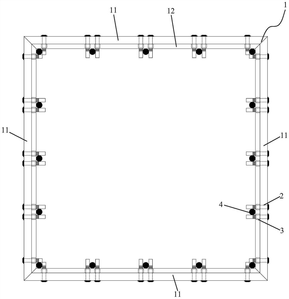
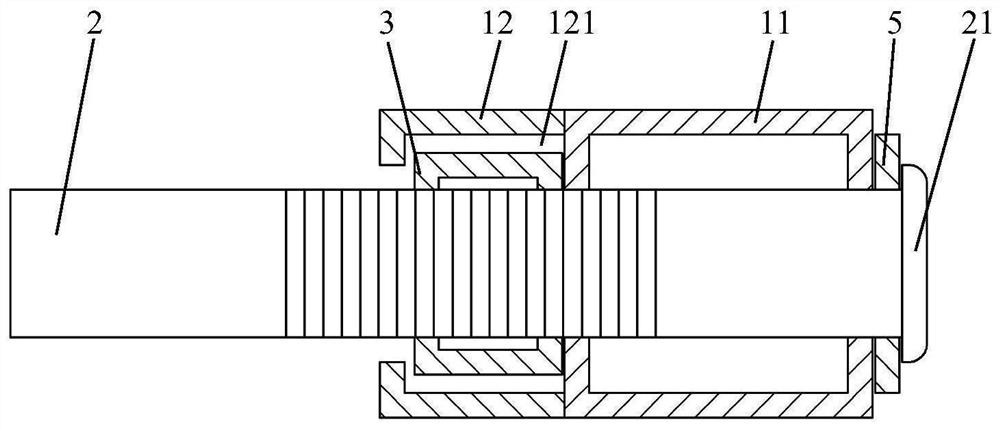
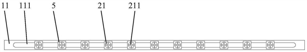
[0032] See attached figure 1 to attach image 3 , the embodiment of the present invention discloses a high-turnover frame column precise positioning device for the main reinforcement, including:

[0033] The main frame 1; the main frame 1 includes a plurality of square tubes 11, which are fixedly connected head to tail; the inner side wall and the outer side wall of the square tube 11 are provided with corresponding strip holes 111 along its length direction;...


PUM


Abstract

The invention discloses an accurate positioning device for high-turnover frame column main reinforcements. The accurate positioning device is characterized in that a main frame comprises a plurality of square and rectangular pipes; corresponding strip-shaped holes are formed in the inner side walls and the outer side walls of the square and rectangular pipes in the length direction of the square and rectangular pipes; strip-shaped baffles with L-shaped sections are symmetrically fixed to the top edges and the bottom edges of the inner side walls of the square and rectangular pipes, and the two strip-shaped baffles and the inner side walls of the square and rectangular pipes form a limiting cavity; multiple bolt rods are arranged and penetrate through the two strip-shaped holes from the outer side walls of the square and rectangular pipes to enter the main frame; the number of the nuts is the same as that of the bolt rods, and the nuts are arranged in the limiting cavity and are in threaded fastening connection with the bolt rods; and the nuts can slide in the length direction of the limiting cavity. The accurate positioning device for the high-turnover frame column main reinforcements is convenient to operate, light in self weight, capable of being freely adjusted according to different sections, the number of steel bars and the distance and high in turnover rate, and meanwhile, the device can effectively limit the steel bars, so that the steel bars are accurately positioned and have small mass deviation.

Description

technical field [0001] The invention relates to the technical field of concrete pouring, in particular to a device for precisely positioning the main reinforcement of a high-turnover frame column. Background technique [0002] In the reinforced concrete structure of engineering construction, the load of beams and slabs is mainly transmitted to walls and columns, and the load of walls and columns is transmitted to the foundation. The frame column is the main vertical support structure, and its main reinforcement is generally provided with positioning stirrups at the root to ensure the cross-sectional size of the column and the relative distance of the reinforcement. When the main reinforcement is installed upward on the frame column, the position of the main reinforcement is easily displaced as the installation height increases. After pouring the beams, slabs, walls, and columns of this layer, the position of the main reinforcement on the upper floor often exceeds the deviat...

Claims


Application Information

Patent Timeline
Patent Type & Authority Applications(China)
IPC IPC(8): E04C5/18
CPCE04C5/18
Inventor 董野解江涛刘小
Owner CHINA CONSTR FIFTH ENG DIV CORP LTD
Why Eureka
Try Eureka