Calibration method for unmanned vehicle

A calibration method and technology for pedestrians, which are applied to measuring devices, instruments, etc., can solve problems such as amplification of positioning errors, difficulty in accurate positioning, and deviation of driving wheels, and achieve the goal of eliminating accumulated errors, accurate running positions, and prolonging service life. Effect

Inactive Publication Date: 2021-08-27
FOCUSED PHOTONICS
View PDF5 Cites 1 Cited by
  • Summary
  • Abstract
  • Description
  • Claims
  • Application Information

AI Technical Summary

Problems solved by technology

[0002] At present, driving is basically driven by a man, and the grasping and positioning rely on manual positioning, which is difficult to locate accurately
At present, part of the driving has been changed to automatic positioning, but there are problems such as positioning error enlargement after long-term operation, driving wheels at both ends of the driving deviation, resulting in rail gnawing, etc.

Method used


Image

  • Calibration method for unmanned vehicle

Examples


Embodiment 1

[0026] The calibration method of the unmanned vehicle in the embodiment of the present invention, the calibration method of the unmanned vehicle is:

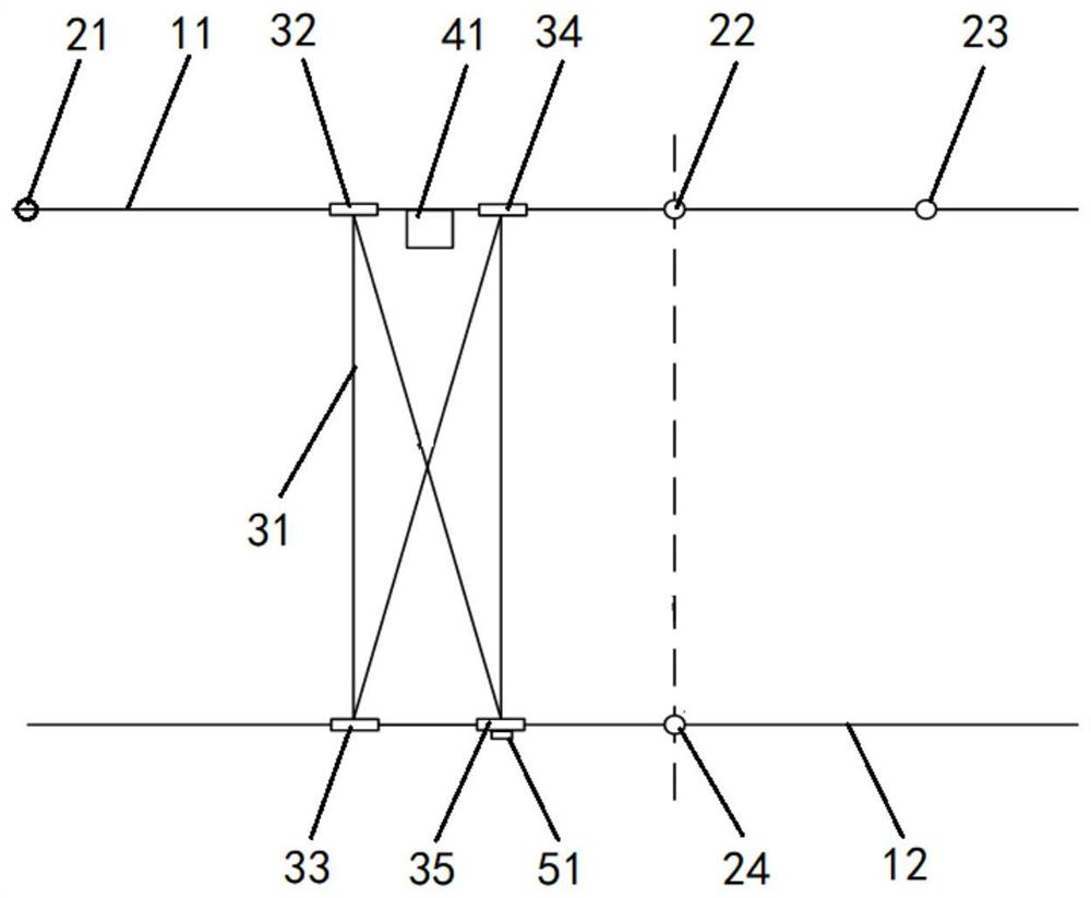
[0027] Such as figure 1 As shown, the two sides of the unmanned vehicle 31 are respectively translated on the first track 11 and the second track 12 to obtain the distance L from the unmanned vehicle to the reference point 21;

[0028] When the unmanned vehicle 31 moves to the first marking point 22, the distance L from the unmanned vehicle 31 to the reference point 21 is obtained at this time 1 ;

[0029] Compare (L 1 -Ls 1 ) and △1, Ls 1 is the distance from the first marking point 22 to the reference point 21, and Δ1 is the allowable maximum position calibration error of the unmanned vehicle 31;

[0030] If (L 1 -Ls 1 )≤△1, no need to calibrate;

[0031] If (L 1 -Ls 1 )>△1, the calibration distance Ls from the unmanned vehicle 31 to the reference point 21=L-(L 1 -Ls 1 );

[0032] When the unmanned vehicle 31 move...

Embodiment 2

[0049] An application example of the calibration method for unmanned vehicles according to Embodiment 1 of the present invention.

[0050] In this application example, if figure 1 As shown, the unmanned vehicle 31 adopts four wheels, and the left rear wheel 32 and the right rear wheel 22 are synchronously driven by the power mechanism. Synchronized with the left front wheel), driven by the power module 51 as required, so as to advance or retreat independently, and then realize the deviation correction function; the left front wheel 34 and the left rear wheel 32 are arranged on the first track 11, the right front wheel 35 and the right Rear wheel 33 is arranged on the second track 12; First track 11 and second track 12 are arranged in parallel; Distance measuring device 41 adopts laser range finder, is arranged on the left side of described unmanned vehicle 31, and on the first track A light reflection component is set at the reference point 21 of 11;

[0051] The reference p...

Embodiment 3

[0071] According to the application example of the calibration method for unmanned vehicles in Embodiment 1 of the present invention, the difference from Embodiment 2 is:

[0072] The power module drives the left front wheel independently according to the needs; when it is necessary to correct the deviation, the right rear wheel of the unmanned vehicle is locked, the left rear wheel is free, and the power module is used to drive the left front wheel back, and the back distance is v△t.


PUM


Abstract

The invention provides a calibration method for an unmanned vehicle. The method specifically comprises the steps of carrying out translation of two sides of the unmanned vehicle on a first track and a second track, and obtaining a distance L from the unmanned vehicle to a reference point; when the unmanned vehicle moves to the first mark point, obtaining the distance L1 from the unmanned vehicle to the reference point at the moment; comparing (L1-Ls1) with [delta]1, wherein Ls1 is the distance from the first mark point to the reference point, [delta]1 is the maximum position calibration error allowed by the unmanned vehicle, if (L1-Ls1) is less than or equal to [delta]1, calibration is not needed, and if (L1-Ls1) is greater than [delta]1, the calibration distance Ls from the unmanned vehicle to the reference point is equal to L-(L1-Ls1); when the unmanned vehicle further moves to the second mark point, obtaining the distance L2 from the unmanned vehicle to the reference point at the moment; and comparing [L2-(L1-Ls1)] with [delta]s1, wherein [delta]s1 is the maximum test error, if [L2-(L1-Ls1)] is less than or equal to [delta]s1, a calculation formula Ls = L-(L1-Ls1) is stored, and if [L2-(L1-Ls1)] is greater than [delta]s1, an alarm is prompted to be given. The method has the advantages of accurate positioning and the like.

Description

technical field [0001] The invention relates to an unmanned vehicle, in particular to a calibration method for an unmanned vehicle. Background technique [0002] At present, driving is basically driven by a man, and the grasping and positioning rely on manual positioning with the naked eye, which is difficult to locate accurately. At present, part of the driving has been changed to automatic positioning, but there are problems such as the positioning error enlargement after long-term operation, and the driving wheels at both ends of the driving deviation, which leads to rail gnawing and other problems. Contents of the invention [0003] In order to solve the shortcomings in the above-mentioned prior art solutions, the present invention provides a calibration method for unmanned vehicles. [0004] The purpose of the present invention is achieved through the following technical solutions: [0005] The calibration method of unmanned vehicle, the calibration method of descri...

Claims


Application Information

Patent Timeline
Patent Type & Authority Applications(China)
IPC IPC(8): G01B21/00
CPCG01B21/00
Inventor 张进伟郑利楠张文军李清华
Owner FOCUSED PHOTONICS
Why Eureka
Try Eureka