TLCC drive circuit with over-temperature automatic protection

An automatic protection and drive circuit technology, applied in the field of drive circuits and TLCC drive circuits with over-temperature automatic protection, can solve the problems of thermal runaway of LED lamps, affecting the reliability and service life of LED lamps, etc., to limit surge interference and realize Effect of shifting power consumption and alleviating the problem of lack of chips

Pending Publication Date: 2021-08-27
杭州火石照明有限公司
View PDF0 Cites 0 Cited by
  • Summary
  • Abstract
  • Description
  • Claims
  • Application Information

AI Technical Summary

Problems solved by technology

In terms of power, this process is a positive feedback process, which will eventually lead to thermal runaway of the LED lamp, affecting the reliability and service life of the LED lamp

Method used


Image

  • TLCC drive circuit with over-temperature automatic protection
  • TLCC drive circuit with over-temperature automatic protection
  • TLCC drive circuit with over-temperature automatic protection

Examples


Embodiment 1

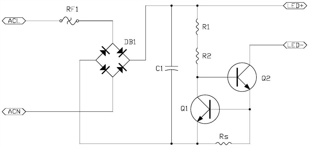
[0023] refer to figure 1 , a TLCC drive circuit with automatic over-temperature protection in the present invention includes a power supply, an over-temperature protection module and an LED load, the over-temperature protection module includes a triode Q1, a triode Q2, a starting resistor group and a constant current resistor Rs, and the The collector of the triode Q1 is connected with the base of the triode Q2 and connected with the anode return terminal of the power supply and the positive terminal of the LED load through the starting resistor group, and the base of the triode Q1 is connected with the emitter of the triode Q2 It is connected to the cathode loop end of the power supply through the constant current resistor Rs, the emitter of the triode Q1 is connected to the cathode loop end of the power supply, and the negative end of the LED load is connected to the collector of the triode Q2.

[0024] The power supply is an AC power supply, and also includes a rectificatio...

Embodiment 2

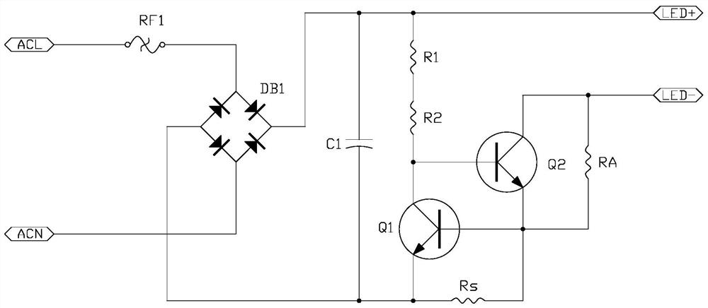
[0040] refer to figure 2 , a shunt resistor RA is connected between the collector of the triode Q2 and the emitter of the triode Q2.

[0041] Others are the same as embodiment one.

[0042] The shunt resistor RA added in parallel between the collector of the transistor Q2 and the emitter of the transistor Q2 in the TLCC drive circuit has a unique function of shunting and dividing power consumption, which can make the positive terminal of the LED load flow into the negative terminal of the LED load. The circuit is divided into two paths. One of the two currents directly flows through the collector of the transistor Q2 to the emitter of the transistor Q2 , while the other current flows through the shunt resistor RA and then flows to the emitter of the transistor Q2 . The two currents are finally brought together at the emitter of the transistor Q2, and then connected to the base of the transistor Q1 to form a loop to the ground through the constant current resistor Rs.

[00...

Embodiment 3

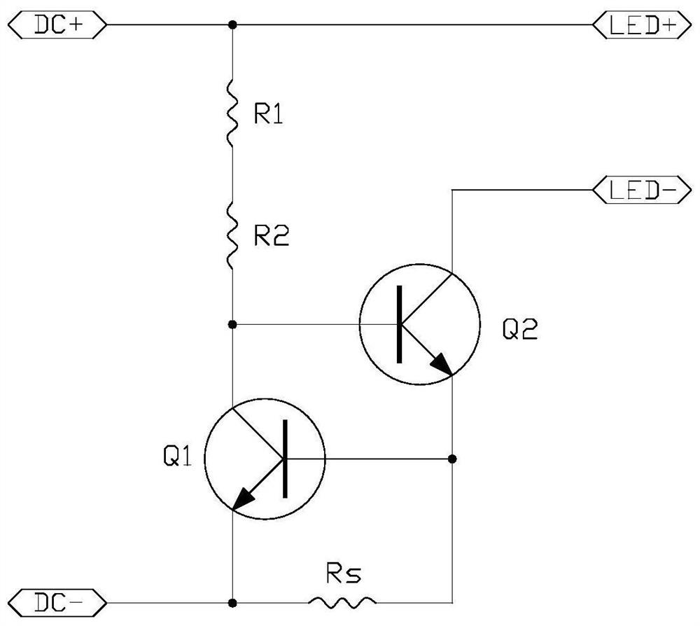
[0045] refer to image 3 , a TLCC drive circuit with automatic over-temperature protection in the present invention includes a power supply, an over-temperature protection module and an LED load, the over-temperature protection module includes a triode Q1, a triode Q2, a starting resistor group and a constant current resistor Rs, and the The collector of the triode Q1 is connected with the base of the triode Q2 and connected with the anode return terminal of the power supply and the positive terminal of the LED load through the starting resistor group, and the base of the triode Q1 is connected with the emitter of the triode Q2 It is connected to the cathode loop end of the power supply through the constant current resistor Rs, the emitter of the triode Q1 is connected to the cathode loop end of the power supply, and the negative end of the LED load is connected to the collector of the triode Q2.

[0046] The power supply is a DC power supply, and the DC+ terminal and DC- term...


PUM


Abstract

The invention discloses an over-temperature automatic protection TLCC drive circuit, which comprises a power supply, an over-temperature protection module and an LED load, and is characterized in that the over-temperature protection module comprises a triode Q1, a triode Q2, a starting resistor group and a constant current resistor Rs; and the collector electrode of the triode Q1 is connected with the base electrode of the triode Q2 and is connected with the anode loop end of the power supply and the positive electrode end of the LED load through the starting resistor group, and the base electrode of the triode Q1 is connected with the emitter electrode of the triode Q2 and is connected with the cathode loop end of the power supply through the constant current resistor Rs. The emitting electrode of the triode Q1 is connected with the cathode loop end of the power supply, the negative electrode end of the LED load is connected with the collecting electrode of the triode Q2, current can be output constantly, and the over-temperature automatic protection characteristic is achieved.

Description

【Technical field】 [0001] The invention relates to the technical field of drive circuits, in particular to the technical field of a TLCC (Triodelinear constant current) drive circuit with automatic over-temperature protection. 【Background technique】 [0002] LED lights are recognized as the fourth-generation green light source, with many advantages such as high efficiency, long life, safety and environmental protection, small size, high reliability, and fast response speed. The technology is mature and widely used in various fields. Since the LED is a constant current load, it must be driven by a constant current to ensure that it always maintains a safe and stable working condition. Existing LED lamp drive circuits usually rely on dedicated constant current drive chips for constant current drive. Therefore, the production capacity of the product is greatly affected by the market supply of the chip, and the price of the product is likely to change with the price increase of t...

Claims


Application Information

Patent Timeline
Patent Type & Authority Applications(China)
IPC IPC(8): H05B45/345H05B45/50H05B45/56
CPCH05B45/345H05B45/50H05B45/56Y02B20/30
Inventor 刘磊
Owner 杭州火石照明有限公司
Why Eureka
Try Eureka